
Clamping device for vehicle body transfer cart

Active Publication Date: 2009-04-16
HYUNDAI MOTOR CO LTD
View PDF4 Cites 4 Cited by
  • Summary
  • Abstract
  • Description
  • Claims
  • Application Information

AI Technical Summary

Benefits of technology

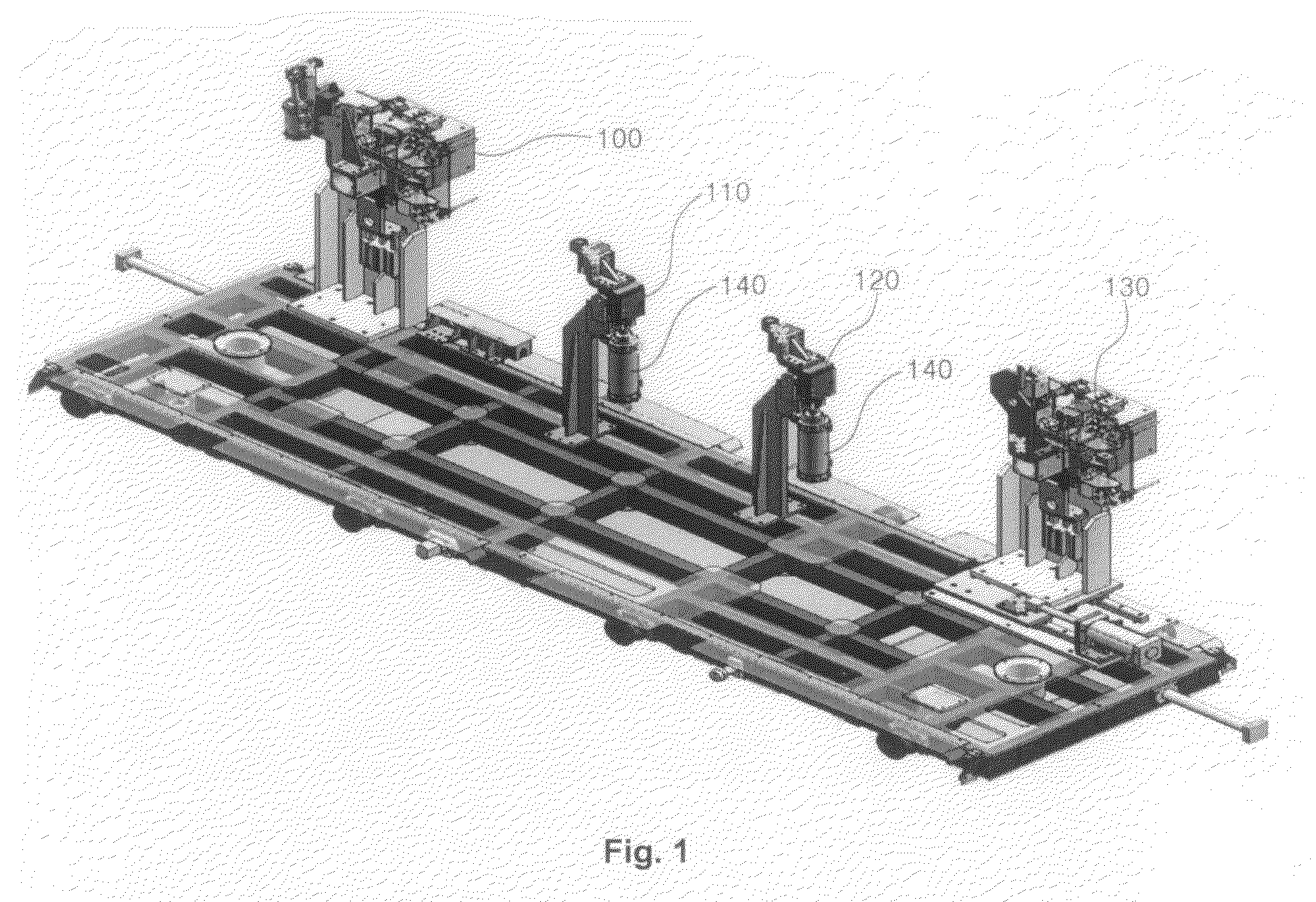
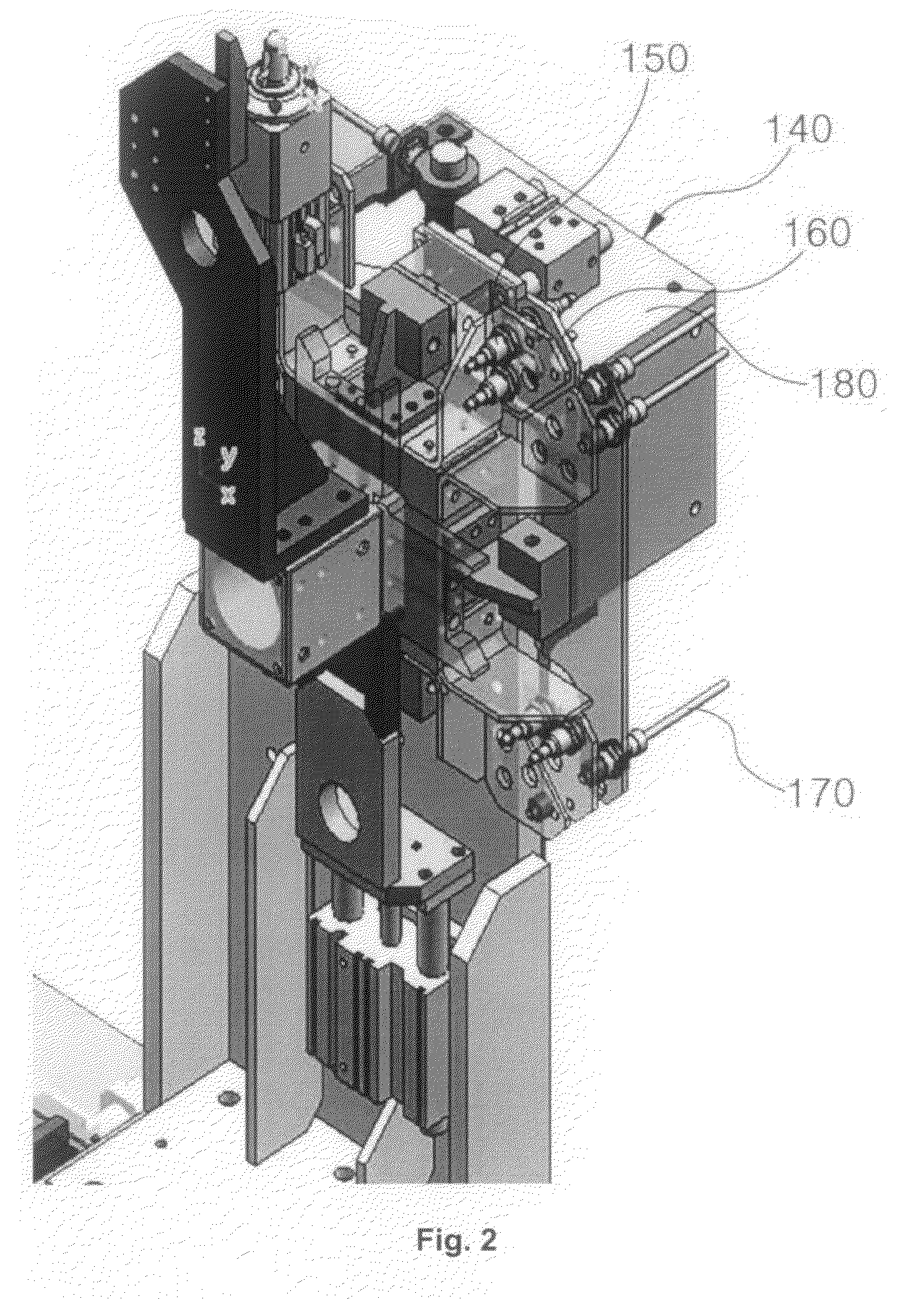
[0021]Accordingly, the present invention has been made in an effort to solve the above-described drawbacks and one object of the present invention is to provide a clamping device for a vehicle body transfer cart, in which a rotation unit for rotating a cart unit, an air supply unit for supplying air to the cart unit, and an electrical signal unit for transmitting an electric signal to the cart unit are installed in a single processing device such that rotation, air supply, and electrical power supply operations are performed in a single process, thus simplifying the structure of the device and improving the structure of the cart unit to reduce the weight of the cart unit.
[0026]More preferably, the air supply unit comprises an air supply cylinder mounted on one side of the rotation unit to supply air, and a second slider mounted on one side of the air supply cylinder to prevent the cart unit from interfering with the air supply cylinder during the entrance of the cart unit.

Problems solved by technology

Meanwhile, most vehicle manufacturing companies do not produce a single kind of vehicle but produce various kinds of vehicles to meet clients' tastes.
It is thus necessary to provide an equipment that can satisfy all kinds of vehicles, but it would impose a heavy economic burden on the companies.
However, the conventional techniques have a problem in that the electric power supply, air supply and rotation operations are not performed in a single process for a cart unit.
Accordingly, in the conventional clamping system, the space for the installation of the plurality of devices is increased and the burden of the transfer device is increased due to the excessive weight of the cart unit.
In the case where the kind of vehicle to be processed is added to utilize the space of each device, the respective devices may interfere with each other.
As a result, the conventional clamping device for the vehicle body transfer cart has problems in that the structure is complicated due to the increase in the number of the components and it takes a lot of time to design the device due to the complicated structure.
Moreover, the manufacturing cost is increased due to the increase in the number of the components, it is difficult to maintain and repair the device, and it occupies a large assembly space.

Method used


Image

  • Clamping device for vehicle body transfer cart
  • Clamping device for vehicle body transfer cart
  • Clamping device for vehicle body transfer cart

Examples


Embodiment Construction

[0035]Reference will now be made in detail to the preferred embodiment of the present invention, examples of which are illustrated in the drawings attached hereinafter, wherein like reference numerals refer to like elements throughout. The embodiments are described below so as to explain the present invention by referring to the figures.

[0036]FIG. 3 is a perspective view of a clamping device for a vehicle body transfer cart in accordance with a preferred embodiment of the present invention, FIG. 4 is a schematic diagram of a rotation unit of the clamping device for a vehicle body transfer cart in accordance with a preferred embodiment of the present invention, FIG. 5 is a front view of the rotation unit of the clamping device for a vehicle body transfer cart in accordance with a preferred embodiment of the present invention, and FIG. 6 is a schematic diagram of an air supply unit and an electric power supply unit of the clamping device for a vehicle body transfer cart in accordance ...


PUM

PropertyMeasurementUnit
Angleaaaaaaaaaa

Abstract

The present invention provides a clamping device for a vehicle body transfer cart, in which a rotation unit for rotating a cart unit, an air supply unit for supplying air to the cart unit, and an electrical signal unit for transmitting an electric signal to the cart unit are installed in a single processing device such that the structure of the device is simplified, the number of components is decreased to reduce manufacturing and installation costs, the structure of the cart unit is improved to be suitable for the clamping device, and thus the weight of the cart unit is reduced.

Description

CROSS-REFERENCE TO RELATED APPLICATION[0001]This application claims under 35 U.S.C. §119(a) on Korean Patent Application No. 10-2007-0103143, filed on Oct. 12, 2007, the entire contents of which are incorporated herein by reference.BACKGROUND[0002](a) Technical Field[0003]The present invention relates to a clamping device for a vehicle body transfer cart. More particularly, the present invention relates to a clamping device for a vehicle body transfer cart, in which a rotation unit, an air supply unit, and an electrical signal unit are installed in a single processing device such that rotation, air supply, and electrical power supply operations are performed in a single process, thus simplifying the structure of the device, reducing the number of components to save manufacturing and installation costs, and simplifying the structure and reducing the weight of a cart unit for the clamping device.[0004](b) Background Art[0005]In general, in order to weld or assemble various components ...

Claims


Application Information

Patent Timeline
IPC IPC(8): B23K9/00
CPCB62D65/18Y10T29/53061Y10T29/49998Y10T29/53039B62D65/00B62D65/02
Inventor HUR, MYEON GI
Owner HYUNDAI MOTOR CO LTD
Learn More