
Brake control method and brake control device

Inactive Publication Date: 2008-05-15
YOKOHAMA RUBBER CO LTD
View PDF15 Cites 8 Cited by
  • Summary
  • Abstract
  • Description
  • Claims
  • Application Information

AI Technical Summary

Benefits of technology

[0019]The brake control method according to the present invention includes the steps of: acquiring, in time series, acceleration data in a radial direction of a tire; setting a predetermined detection range with respect to the acceleration data; specifying a corresponding part of the acceleration data falling within the detection range; and controlling, in a case where a value of the specified acceleration data is larger than the threshold value, a brake force. Accordingly, after the detection range and the threshold value are set, it is only necessary to specify the corresponding part of the acceleration data falling within the detection range and to compare a value of the data with the threshold value. Therefore, it is not necessary to perform frequency analysis, which makes it possible to perform control on the brake to be put on a vehicle with the speed of control operation of a brake force increased. As a result, the brake control device can be simplified in structure. As described above, the present invention is different from the conventional art in that the present invention is capable of controlling a brake force of a brake without performing frequency analysis for extracting high frequency components.
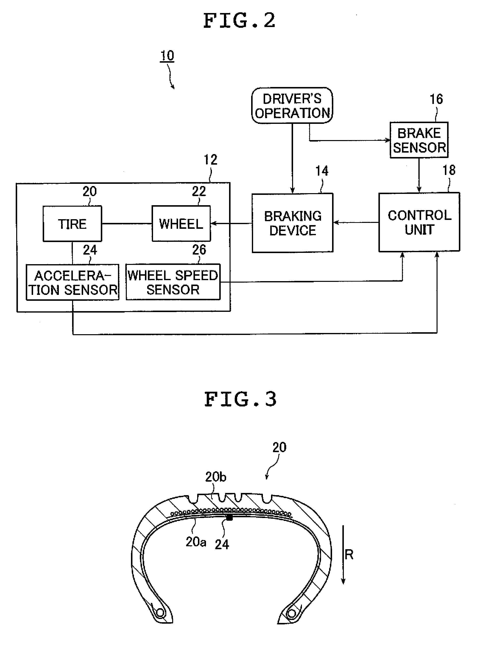
[0020]The brake control device according to the present invention includes: a braking device having a function of applying a brake force to a wheel equipped with a tire to put a brake on the wheel while adjusting the brake force; an acceleration sensor for outputting acceleration data in a radial direction of the tire; and a detection range setting unit for setting a predetermined detection range with respect to the acceleration data and setting a threshold value with respect to a value of a corresponding part of the acceleration data falling within the detection range. The brake control device specifies part of the acceleration data falling within the detection range, compares a value of the specified part of the acceleration data with the threshold value. In the case where the value of the specified part of the acceleration data is larger than the threshold value, the control unit outputs a control signal for causing the braking device to adjust a brake force. Accordingly, after the detection range and the threshold value are set, it is merely necessary to compare only the value of the part of the acceleration data falling within the detection range with the threshold value, with the result that the brake to be put on a vehicle is controlled with the speed of control operation of the brake force increased. Further, it is not necessary to perform frequency analysis, which makes it possible to simplify the structure of the device. As described above, according to the present invention, it is possible to control a brake force of a braking device without performing frequency analysis for extracting high frequency components.

Problems solved by technology

In general, it is difficult for a driver to detect the slide skid behavior.
Further, once the skid behavior has occurred, it is difficult to suppress the skid behavior to return the steering to a controllable state.
As a result, the steering of the vehicle goes out of control, often resulting in a car crash.
However, in any one of the vehicle control devices disclosed in JP 2003-182476 A and JP 2005-306160 A, a frequency analysis is performed on a signal detected by the acceleration sensor, by frequency-analyzing the signal by the frequency analyzing means, or by extracting high frequency components from the signal, which leads to a problem that it is impractical because it takes time to start control of the vehicle.

Method used


Image

  • Brake control method and brake control device
  • Brake control method and brake control device
  • Brake control method and brake control device

Examples


Embodiment Construction

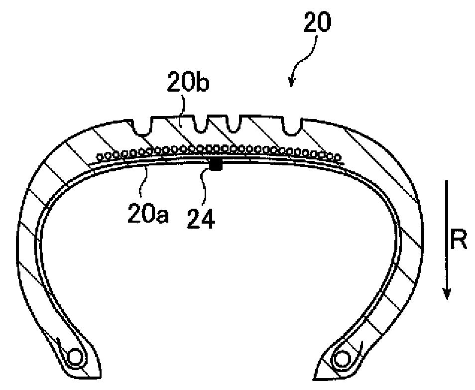
[0039]Hereinbelow, a brake control method and a brake control device according to the present invention are described in detail based on a preferred embodiment with reference to the accompanying drawings.

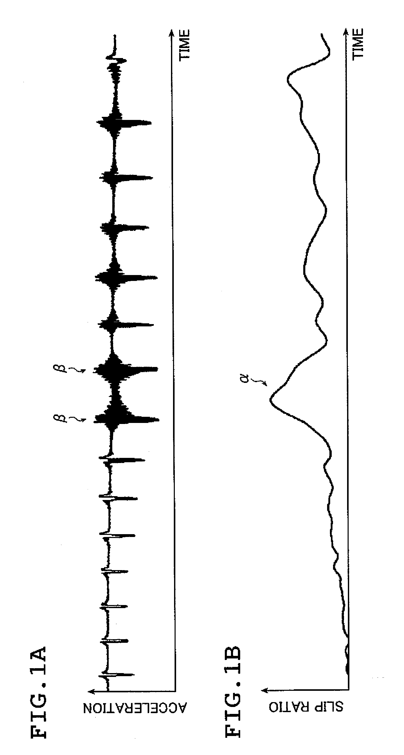
[0040]FIGS. 1A and 1B are graphs each showing acceleration data in the radial direction of a tire and a slip ratio of the tire in relation to the acceleration data, respectively, the data being acquired when a brake is put on a wheel of the tire rotating at 100 km / h.

[0041]The graph of FIG. 1A shows acceleration in the radial direction of the tire, the graph having acceleration on the vertical axis and time on the horizontal axis. The graph of FIG. 1B shows a slip ratio of the tire, the graph having a slip ratio on the vertical axis and time on the horizontal axis. The waveform of the slip ratio shown in FIG. 1B corresponds in timing to the acceleration data shown in FIG. 1A.

[0042]When a brake is put on the tire rotating at 100 km / h, in a region α where a slip ratio is large as shown...


PUM


Abstract

A brake control device is provided to a wheel equipped with a tire, which has a function of applying a brake force to the wheel to put a brake thereon while adjusting the brake force. In the device, an acceleration sensor outputs acceleration data in a radial direction of the rotating tire, a predetermined detection range is set with respect to the acceleration data, a threshold value is set with respect to a corresponding part of the acceleration data falling within the detection range, the corresponding part of the acceleration data falling within the detection range is specified. Values of the specified acceleration data are compared with the threshold value, and a control signal for causing a braking device to adjust the brake force thereof is output in a case where some values of the acceleration data are larger than the threshold value.

Description

CROSS REFERENCE TO RELATED APPLICATION[0001]This application claims the benefit and priority to Japanese Application Number 2006-308083, filed on Nov. 14, 2006, the disclosure of which is hereby incorporated by reference in its entirety.BACKGROUND OF THE INVENTION[0002]The present invention relates to a brake control method and a brake control device, which are used for a braking device provided to a vehicle or the like, the braking device having a function of applying a brake force to a wheel equipped with a tire to put a brake thereon while adjusting the brake force, and more particularly, to a brake control method and a brake control device capable of controlling a brake force to be applied to a wheel without performing frequency analysis.[0003]When a vehicle is making a turn, a tread portion of a tire provided with a slip angle partially slips on a road surface. In other words, the tread portion of the tire provided with a slip angle has a contact region formed of a region in wh...

Claims


Application Information

Patent Timeline
IPC IPC(8): B60T8/171G06F19/00B60T8/172B60T8/1761B60T8/32
CPCB60T8/172B60T8/17616Y10T152/10279Y10T152/10B60T2210/12
Inventor KITAZAKI, TSUYOSHIMATSUDA, JUNMIYASHITA, NAOSHIHASHIMURA, YOSHIAKI
Owner YOKOHAMA RUBBER CO LTD
Learn More