Method and Device for Manufacturing an Assembly of Two Ringed Sheaths That Can Be Detached From One Another to Make a Single Ringed Sheath

Inactive Publication Date: 2009-04-16
DELFINGEN FR ANTEUIL
View PDF1 Cites 11 Cited by
  • Summary
  • Abstract
  • Description
  • Claims
  • Application Information

AI Technical Summary

Benefits of technology

[0013]A first cut-out internal ringed sheath is placed on the cabling which is to be protected. The second cut-out external ringed sheath is thus detached from the first and then placed thereon. The external ringed sheath largely covers the internal ringed sheath in such a way as to prevent cables from escaping, in particular when the bundle of cables passes into regions with a low radius of curvature. This double pr

Problems solved by technology

However, it is difficult to thread the strand within the ringed sheath, in particular in long portions.
These closing systems have been found to be relatively ineffective in regions with low radii o

Method used


Image

  • Method and Device for Manufacturing an Assembly of Two Ringed Sheaths That Can Be Detached From One Another to Make a Single Ringed Sheath
  • Method and Device for Manufacturing an Assembly of Two Ringed Sheaths That Can Be Detached From One Another to Make a Single Ringed Sheath
  • Method and Device for Manufacturing an Assembly of Two Ringed Sheaths That Can Be Detached From One Another to Make a Single Ringed Sheath

Examples


Example

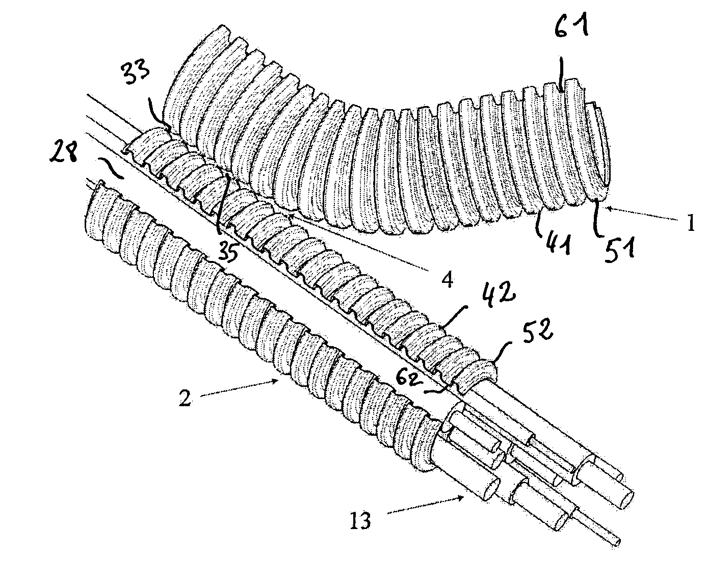
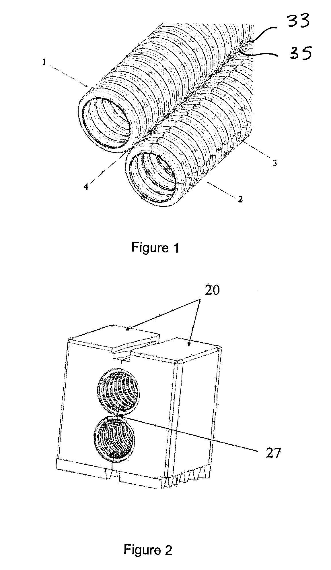
[0029]In one embodiment of the invention, with reference to FIGS. 1, 7, 8, 9, 10 and 12, the protective sheath 12 is obtained by double extrusion of two ringed sheaths 1, 2, an intermittent material connection 4 alternating between material bridges 33 and empty spaces 35 and continuing to connect these two sheaths at a low thickness along a longitudinal axis after extrusion. Preferably, this connection 4 connects the two ringed sheaths 1, 2 only at the peaks 51, 52 of the respective rings 41, 42 thereof between two troughs 61, 62. Two material strips 9 are respectively removed from the two sheaths 1, 2, in order to allow the internal sheath 2 to be placed easily on the cabling 13 which is to be protected, and to allow the external sheath 1 to cover the internal sheath 2. Preferably, the shape and diameter of the internal sheath 2 are adapted so as to allow an optimal position thereof in the external sheath 1, the external height and width of the rings thereof being slightly lower th...


PUM

PropertyMeasurementUnit
Lengthaaaaaaaaaa

Abstract

Method for manufacturing an assembly of two ringed sheaths (1,2) ready to be used to make a single ringed sheath around for example a bundle of electric cables (13), wherein two smooth-walled tubes are simultaneously extruded using a single extruder fitted with two extrusion nozzles, the two smooth-walled tubes are simultaneously moulded into two ringed wall tubes using a moulder equipped with moulds each fitted with two ringed profiles extending in parallel in a longitudinal direction and being paired along one and the same parting line. According to the invention, during moulding, material bridges (33) and empty spaces (35) are created between first tube rings (41) and second tube rings (42), by opening or closing respectively, between the two ringed profiles, material runs formed in the parting line of two paired moulds, a longitudinal strip (28) of ringed tube wall is cut out and removed, using cutting means and the two ringed tubes connected to each other by the material bridges (33) formed between the rings are cut to a desired length, using severing means.

Description

CROSS REFERENCE TO RELATED APPLICATIONS[0001]This application is a Continuation application of PCT / EP2007 / 003154 filed Apr. 10, 2007, claiming priority of FR 0603386 filed Apr. 18, 2006, which are incorporated by reference herein in their entirety.BACKGROUND OF THE INVENTION[0002]1. Field of the Invention[0003]The present invention relates to a method and a device for manufacturing an assembly of two ringed sheaths that can be detached from one another to make a single ringed sheath around a bundle of electric cables for example.[0004]More specifically, in the method of the invention, two smooth-walled tubes are simultaneously extruded using an extruder fitted with two extrusion nozzles and the two smooth-walled tubes are simultaneously moulded into two ringed-wall tubes using a moulder equipped with moulds each fitted with two ringed profiles extending in parallel in a longitudinal direction and being paired along the same mating plane.[0005]2. Description of the Related Art[0006]I...

Claims


Application Information

Patent Timeline
IPC IPC(8): B29C47/12B29D23/18H02G3/04F16L11/00B29C48/30B29C48/09B29C48/32
CPCB29C47/0023B29K2995/0082B29C47/0038B29C47/0066B29C47/126B29C49/0021B29C2793/0036B29C2793/0063B29C2793/009B29D23/18B29K2023/12B29L2023/18B29L2031/602H02G3/0468B29C47/065B29C47/0033B29C48/09B29C48/13B29C48/001B29C48/0022B29C48/21B29C48/303B29C2793/0054B29C49/48185
Inventor BAVEREL, CHRISTOPHEREMY, BENOIT
Owner DELFINGEN FR ANTEUIL
Why Eureka
Try Eureka