Wheel suspension

a technology of wheel suspension and lateral force, which is applied in the direction of resilient suspension, interconnection system, vehicle components, etc., can solve the problems of loss of valuable lateral force potential of tires and loss of vehicle wheels, and achieve the effect of preventing incorrect positions of vehicle wheels

Inactive Publication Date: 2009-04-16
ZF FRIEDRICHSHAFEN AG
View PDF15 Cites 6 Cited by
  • Summary
  • Abstract
  • Description
  • Claims
  • Application Information

AI Technical Summary

Benefits of technology

[0008]The basic object of the present invention is to provide a wheel suspension for a motor vehicle, whose kinematics makes possible an optimal contact o...

Problems solved by technology

The king pin angle becoming established at the vehicle wheel leads to a change in the tire contact surface, so that the vehicle wheel loses valuable adhesion to the ground.
However, this leads to drawbacks during the straight-line travel of the motor vehicle, namely, when individual vehicle...

Method used


Image

  • Wheel suspension
  • Wheel suspension
  • Wheel suspension

Examples


Embodiment Construction

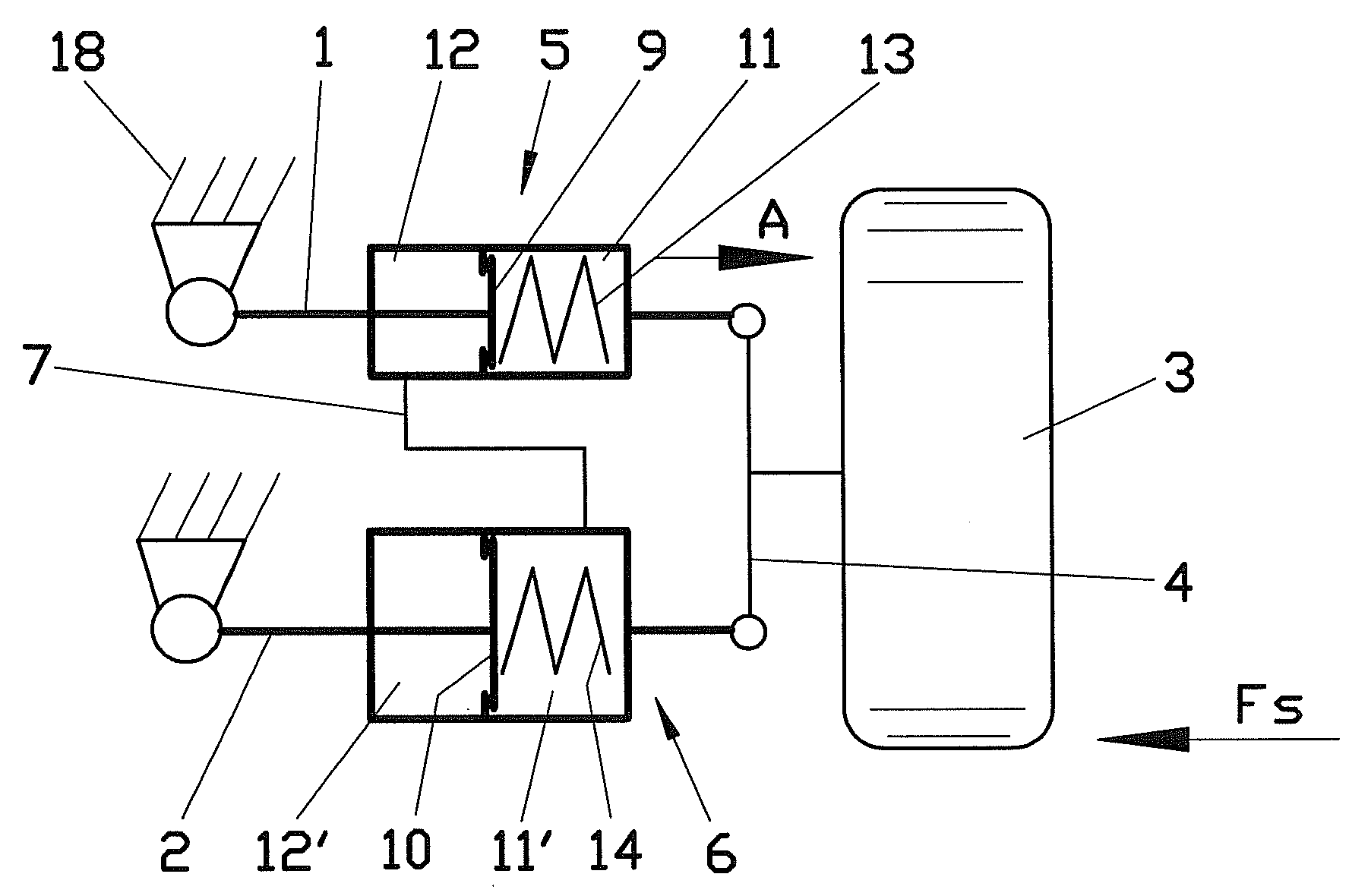
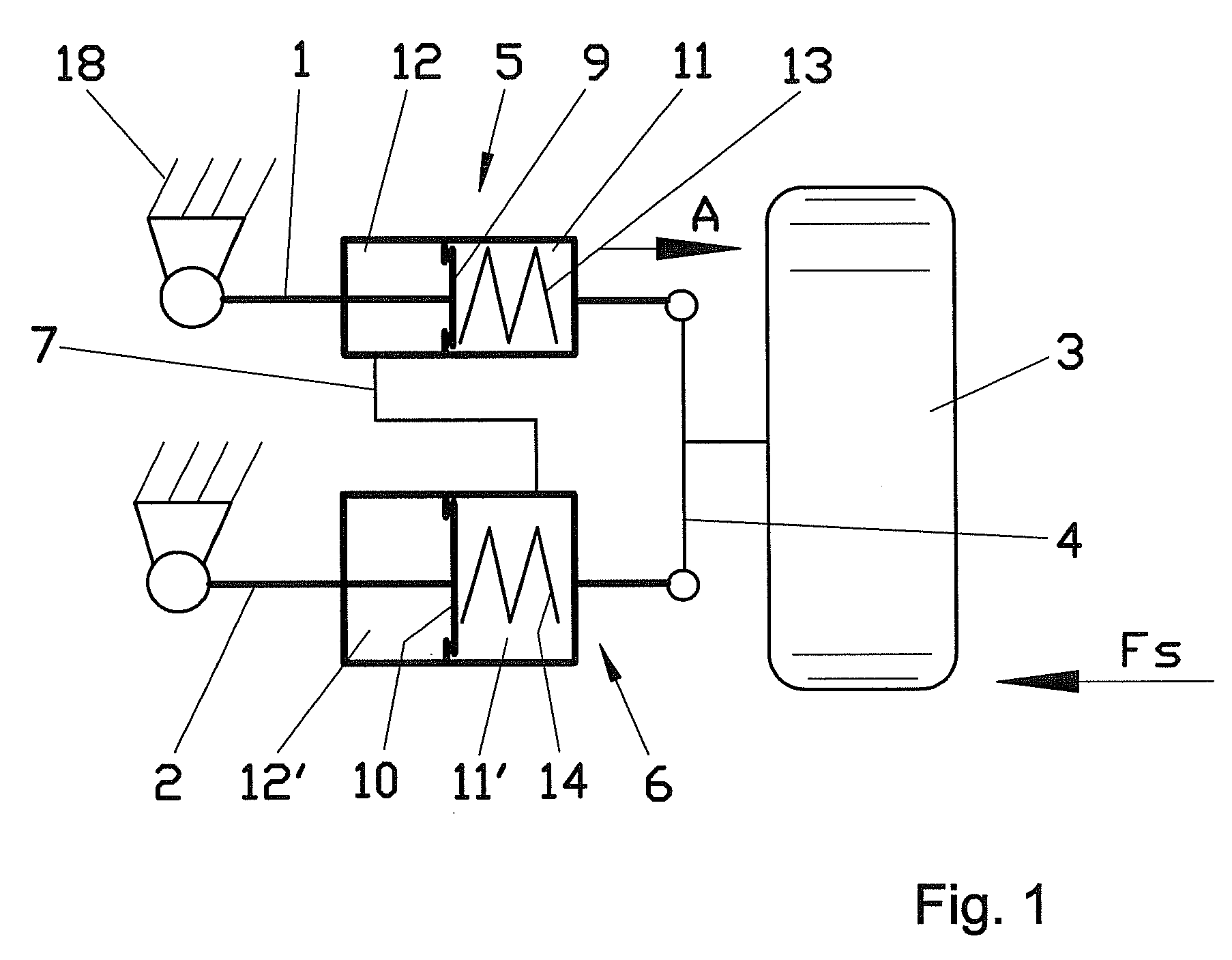
[0036]Referring to the drawings in particular, the simplified view of a non-deflected wheel suspension, which is shown in FIG. 1, has a vehicle wheel 3, which is arranged on a wheel carrier 4. The wheel carrier 4 is articulated to a first control arm 1 and is likewise articulated to a second control arm 2. The first and second control arms form in the example the upper suspension arm 1 and the lower suspension arm 2 of a double wishbone wheel suspension, which represents a specific design of a single-wheel suspension.

[0037]The peculiarity of the wheel suspension shown in FIG. 1 is that the control arms 1 and 2 have a single-acting piston-and-cylinder unit each, which are used as a hydraulic compensating means 5 and 6, respectively. These piston-and-cylinder units 5, 6 are used to correct undesired wheel positions, for example, a king pin angle that becomes established during travel in a curve. A separate piston-and-cylinder unit 5, 6 is integrated in each of the control arms 1, 2 in...


PUM


Abstract

A wheel suspension for a motor vehicle is described, in which at least a first and at least a second control arm (1, 2) are coupled in an articulated manner to a wheel carrier (4) carrying a vehicle wheel (3). The wheel suspension has a compensating device (5, 6) for correcting wheel positions, and each control arm (1, 2) has a portion of the compensating device (5, 6) or is connected to a portion of the compensating device (5, 6). The compensating device portions (5, 6) of one wheel are connected to one another by at least one coupling member (7, 8).

Description

CROSS REFERENCE TO RELATED APPLICATIONS[0001]This application is a United States National Phase application of International Application PCT / DE2007 / 000188 and claims the benefit of priority under 35 U.S.C. § 119 of German Patent Application DE 10 2006 006 513.1 filed Feb. 10, 2006, the entire contents of which are incorporated herein by reference.FIELD OF THE INVENTION[0002]The present invention pertains to a wheel suspension for a motor vehicle, in which at least one first and at least one second control arm are connected in an articulated manner to a wheel carrier carrying a vehicle wheel.BACKGROUND OF THE INVENTION[0003]As a consequence of higher requirements in terms of safety and comfort, interfering effects acting on the wheel suspension must be compensated increasingly better and in increasingly shorter units of time. For example, the inclination of a vehicle wheel relative to the road surface also changes, for example, due to effects of lateral forces and the roll of the veh...

Claims


Application Information

Patent Timeline
IPC IPC(8): B60G3/18
CPCB60G3/18B60G7/003B60G7/006B60G21/007B60G2206/1116B60G2200/46B60G2204/143B60G2204/421B60G2204/422B60G2200/144B62D17/00
Inventor HAEUSLER, FELIXELBERS, CHRISTOPHHEIDSIECK, KNUTARAMAH, SIMON
Owner ZF FRIEDRICHSHAFEN AG
Why Eureka
Try Eureka