Charging device for electric automobile

a charging device and electric automobile technology, applied in electric devices, battery/fuel cell control arrangements, electric devices, etc., can solve the problems of increasing the number of terminals exposed to the exterior of the vehicle, increasing the number of terminals, so as to reduce the number of vehicle side connectors and the number of connection terminals, and the charging capacity of the storage device of the electric automobile decreases.

Active Publication Date: 2009-04-16
SUBARU CORP
View PDF8 Cites 53 Cited by
  • Summary
  • Abstract
  • Description
  • Claims
  • Application Information

AI Technical Summary

Benefits of technology

[0018]According to the present invention, the connector comprising the common connection terminal, to which the fast charging line and the normal charging line are respectively connected, is provided in the vehicle such that when the connection plug of the fast charger is attached to the connector, the fast charging line is switched to a connected state by the switching means, and when the normal charging connection plug is attached to the connector, the normal charging line is switched to a connected state by the switching means. Hence, when either the connection plug of the fast charger or the normal charging connection plug is attached to the connector, one of the fast charging line and the normal charging line is controlled to a connected state in accordance with the type of the connection plug, and therefore any of a plurality of types of connection plug can be attached to the single connector having the common connection terminal, enab

Problems solved by technology

An AC 100V commercial power supply is widely distributed and can be used anywhere, which is convenient for charging, but a power supply amount thereof per unit time is limited, and therefore an AC 100V commercial power supply is not suitable for fast charging during which a large supply of power is required.
This is problematic in that the connection terminal must be selected at the time of charging in accordance with the charging method, and the number of terminals exposed to the exterior of the vehicle increases.
In an electric automobile, meanwhile, when the charging capacity of the battery decreases such that the battery goes flat, t

Method used


Image

  • Charging device for electric automobile
  • Charging device for electric automobile
  • Charging device for electric automobile

Examples


Embodiment Construction

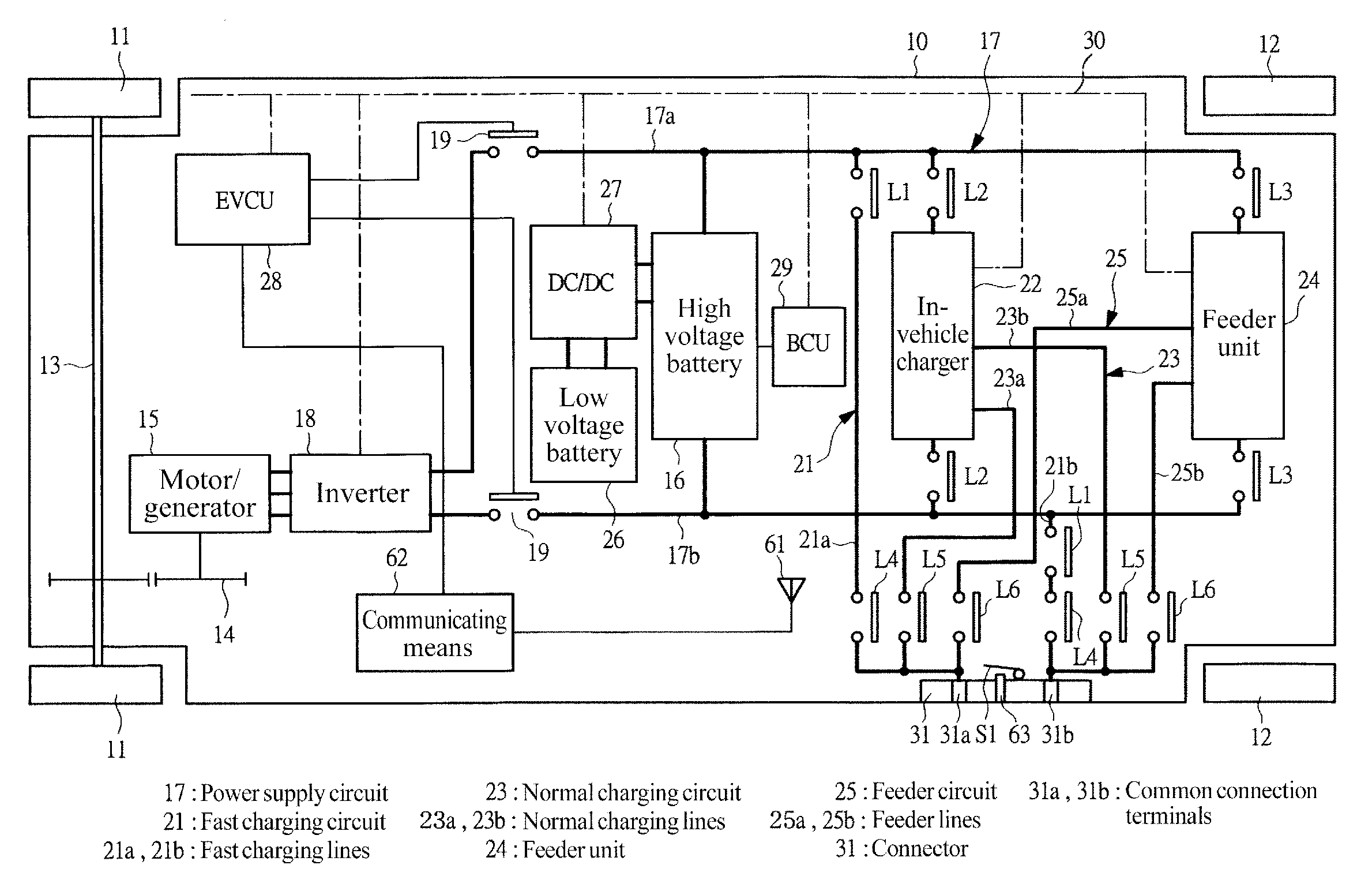
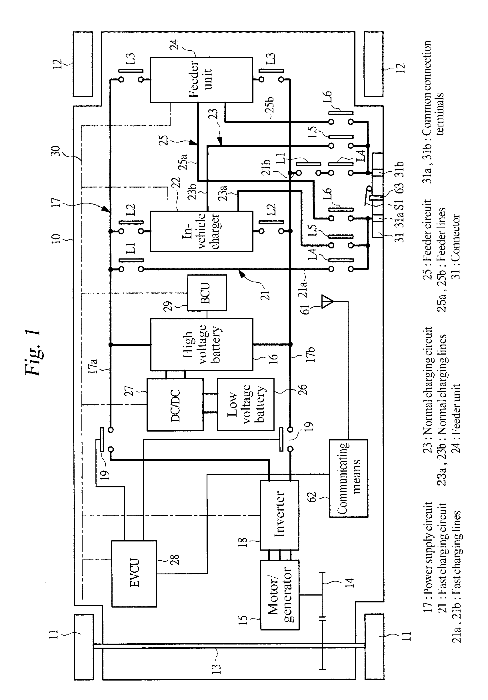
[0026]An embodiment of the present invention will be described in detail below on the basis of the drawings. FIG. 1 is a schematic diagram showing a charging device for an electric automobile according to an embodiment of the present invention. An electric automobile 10 has drive-wheel side front wheels and driven-wheel side rear wheels 12, and a motor / generator is connected to a drive shaft 13 for driving the front wheels via a gear pair 14 having a fixed gear ratio. The motor / generator 15, which serves as a vehicle-driving electric motor, is a three-phase alternating current synchronous motor, and a high voltage battery 16 for supplying power thereto is installed in the vehicle 10 as a storage device. The high voltage battery 16 employs a lithium ion battery, i.e. a secondary battery, and supplies 400V of direct current power, for example, to the motor / generator 15 serving as the load by connecting a plurality of single cell batteries, which are the smallest units of a battery, in...


PUM


Abstract

The present invention provides a charging device for an electric automobile that can reduce the number of connection terminals provided in a vehicle and respond to a plurality of charging methods including normal charging and fast charging. Fast charging lines, an in-vehicle charger, and a feeder unit are connected to a power supply circuit for supplying power from a high voltage battery to a motor/generator. The fast charging lines, normal charging lines connected to the in-vehicle charger, and feeder lines connected to the feeder unit are respectively connected to common connection terminals of a connector. Relays provided on the respective lines are activated in accordance with the type of a connection plug attached to the connector, and as a result, charging is performed in accordance with the type of the connection plug.

Description

CROSS-REFERENCE TO RELATED APPLICATIONS[0001]The disclosure of Japanese Patent Application No. 2007-264062, filed on Oct. 10, 2007 including the specification, drawings and abstract, is incorporated herein by reference in its entirety.BACKGROUND OF THE INVENTION[0002]1. Field of the Invention[0003]The present invention relates to a charging device for an electric automobile, which charges a storage device for supplying power to an electric motor for driving a vehicle.[0004]2. Description of the Related Art[0005]Electric automobiles include vehicles that employ only an electric motor as a drive source and hybrid vehicles having both an electric motor and an engine as drive sources. In both types of electric automobile, a storage device such as a battery is provided to supply power to the electric motor, and when the residual capacity of the battery decreases, the battery must be charged from the outside. In a hybrid vehicle having both an electric motor and an engine as drive sources...

Claims


Application Information

Patent Timeline
IPC IPC(8): H02J7/14H02J7/00
CPCB60L11/1803Y02T90/14B60L11/185B60L11/1868B60L2210/12B60L2210/14B60L2220/14H02J7/02Y02T10/7005Y02T10/7066Y02T10/7225Y02T10/7233Y02T90/121Y02T90/127Y02T90/128B60L11/1818B60L50/51B60L53/11B60L53/16B60L58/20H02J7/0036Y02T10/70Y02T10/7072Y02T10/72H02J5/00Y02T90/12
Inventor SAKURAI, MASATO
Owner SUBARU CORP
Why Eureka
Try Eureka