Motion picture encoding apparatus and motion picture decoding apparatus

a motion picture and encoding technology, applied in the field of motion picture encoding apparatus and motion picture decoding apparatus, can solve the problems of lossless encoding, insufficient compression quality, virtually impossible,

Inactive Publication Date: 2009-04-16
YAMADA YOSHIHISA +3
View PDF12 Cites 50 Cited by
  • Summary
  • Abstract
  • Description
  • Claims
  • Application Information

AI Technical Summary

Benefits of technology

[0015]Accordingly, it is possible to perform an optimal encoding process using a transform scheme most suitable for the characteristics of an image signal.
[0043]Accordingly, it is possible to decode encoded data properly, by switching between variable length decoding schemes, in addition to switching between inverse transform schemes.

Problems solved by technology

Thus, there is a problem in that the quality of compression is insufficient when a signal not adapted to DCT transform characteristics is input.
Another problem is that, with a related-art combination of DCT and quantization, lossless encoding, in which a coding error is zero, is virtually impossible.

Method used


Image

  • Motion picture encoding apparatus and motion picture decoding apparatus
  • Motion picture encoding apparatus and motion picture decoding apparatus
  • Motion picture encoding apparatus and motion picture decoding apparatus

Examples


first embodiment

[0053]FIG. 3 is a block diagram showing a construction of an image encoding apparatus according to a first embodiment of the present invention.

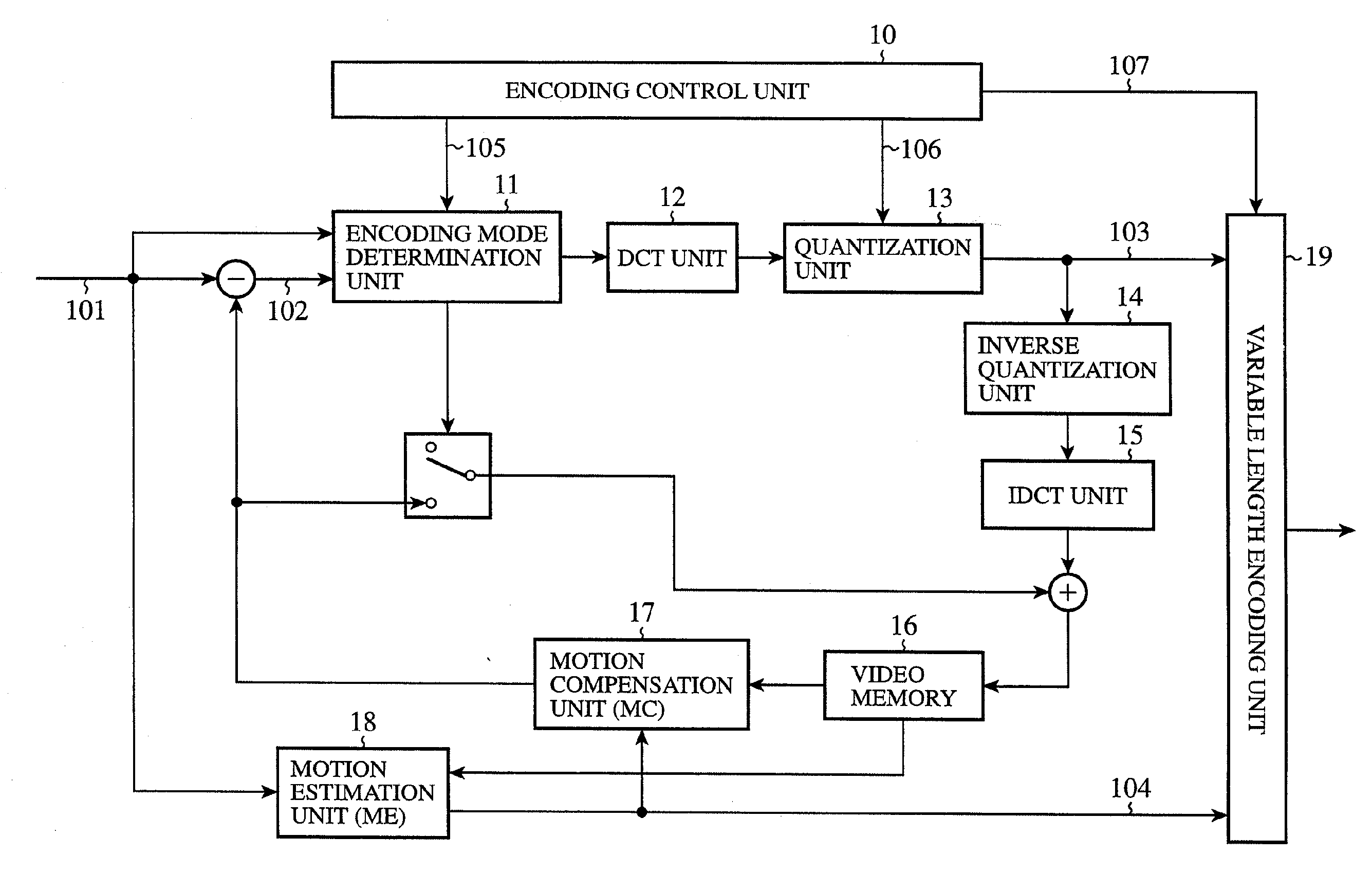
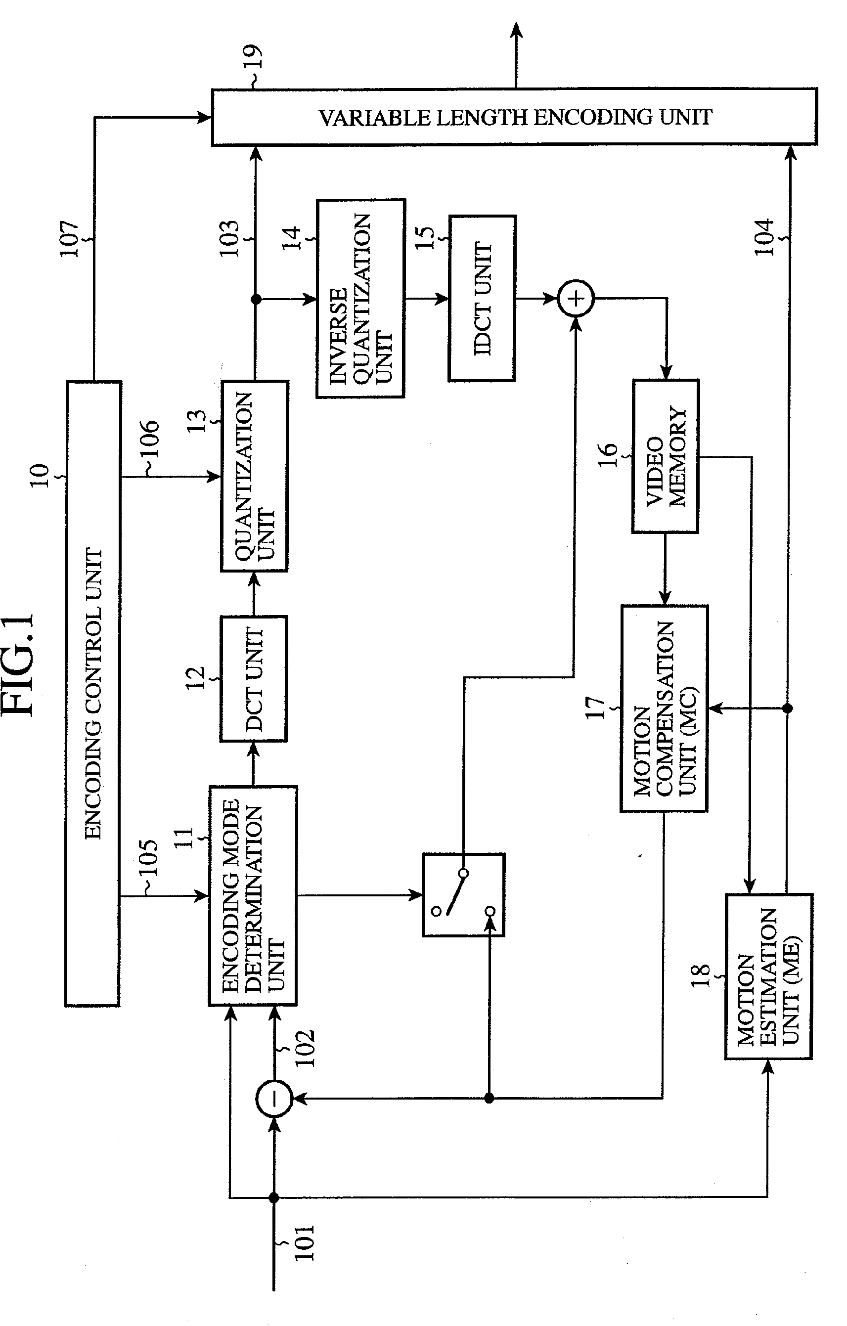
[0054]Referring to FIG. 3, the image encoding apparatus comprises a transform scheme control unit 21, a first transform unit A 22, a second transform unit B 23, a first inverse transform unit A 24, a second inverse transform unit B 25, a switch 26 for selecting either the transform units A 22 or the transform unit B 23, and a switch 27 for selecting either the inverse transform unit A 24 or the inverse transform unit B 25. The other components are identical to the corresponding components of the related art shown in FIG. 1. Blocks with like numerals have like functions and perform like operations.

[0055]A description will now be given of the operation according to the first embodiment. The transform scheme control unit 21 controls the switch 26 using a signal 202, so as to use either the transform unit A 22 or the transform unit B 23 for trans...

second embodiment

[0063]FIG. 4 is a block diagram showing a construction of an image encoding apparatus according to a second embodiment of the present invention. Referring to FIG. 4, a difference from the first embodiment is that a transform scheme control unit 31 operates in accordance with a signal from an encoding control unit 30. With this, transmission of the transform scheme selection flag 201 to a decoding apparatus, required in the first embodiment, is unnecessary or the frequency of transmission is reduced.

[0064]A description will now be given of the operation of the encoding control unit 30 and the transform scheme control unit 31 according to the second embodiment. The transform scheme control unit 31 controls the switches 26 and 27 in accordance with a signal 203 from the encoding control unit 30. Some examples will be given below of how the transform scheme control unit 31 controls the operation based on the signal 203 from the encoding control unit 30.

(1) Control Based on the Quantizat...

third embodiment

[0072]FIG. 5 is a block diagram showing a construction of an image encoding apparatus according to the third embodiment. Referring to FIG. 5, the apparatus is identical with the apparatus according to the first embodiment shown in FIG. 3 except provisions of an encoding control unit 40, two quantization units 42 and 43, two inverse quantization units 44 and 45 and elimination of the switch 27. The encoding control unit 40 uses the signal 213 to select the quantization unit A 42 and signal 214 to select the quantization unit B 43.

[0073]A description will now be given of the operation according to the third embodiment. For example, when the switch 26 selects the first transform unit A 22 in accordance with the signal 202 from the transform scheme control unit 21, the signal transformed by the first transform unit A 22 is subject to quantization adapted to the transform scheme. More specifically, the signal is quantized by the quantization unit A 42 providing a better coding efficiency...


PUM


Abstract

A motion picture encoding apparatus for encoding a motion picture signal includes a plurality of transform units for different transform schemes, and a transform scheme control unit for selecting, from the plurality of the transform units, the transform unit for the transform scheme adapted to the motion picture signal.

Description

[0001]This application is a Divisional of co-pending application Ser. No. 10 / 469,811 filed on Sep. 4, 2003, and for which priority is claimed under 35 U.S.C. § 120; and this application claims priority of Application No. 2002-000516 filed in Japan on Jan. 7, 2002 under 35 U.S.C. § 119; the entire contents of all are hereby incorporated by reference.[0002]The present invention relates to a motion picture encoding apparatus for compressing a motion picture signal for transmission and a motion picture decoding apparatus for expanding the compressed motion picture signal for reproduction.BACKGROUND ART[0003]FIG. 1 is a block diagram showing a construction of a related-art motion picture encoding apparatus shown, for example, in the International Standard ISO / IEC 13818-2 (also known as MPEG-2 video part). The encoding apparatus comprises an encoding control unit 10, an encoding mode determination unit 11, a DCT unit 12, a quantization unit 13, an inverse quantization unit 14, an inverse ...

Claims


Application Information

Patent Timeline
Patent Type & Authority Applications(United States)
IPC IPC(8): H04N11/02H04N7/26G06T9/00H04N19/12H03M7/30H03M7/40H04N19/126H04N19/13H04N19/134H04N19/136H04N19/139H04N19/14H04N19/146H04N19/159H04N19/16H04N19/166H04N19/172H04N19/174H04N19/176H04N19/177H04N19/423H04N19/46H04N19/503H04N19/51H04N19/513H04N19/577H04N19/593H04N19/60H04N19/61H04N19/625H04N19/70H04N19/85H04N19/90H04N19/91
CPCH04N19/197H04N19/137H04N19/159H04N19/172H04N19/46H04N19/196H04N19/13H04N19/122H04N19/129H04N19/61H04N19/107H04N19/112H04N19/12H04N19/463H04N19/126H04N19/105H04N19/625
Inventor YAMADA, YOSHIHISAMORIYA, YOSHIMISUGIMOTO, KAZUOASAI, KOHTARO
Owner YAMADA YOSHIHISA
Why Eureka
Try Eureka