Error Compensation Method, Digital Phase Error Cancellation Module, and ADPLL thereof

a digital phase error and compensation method technology, applied in the direction of phase difference detection angle demodulation, automatic control of pulses, electrical devices, etc., can solve the problem that the analog pll is easy to have errors (or even error propagation)

Inactive Publication Date: 2009-04-16
MEDIATEK INC
View PDF38 Cites 41 Cited by
  • Summary
  • Abstract
  • Description
  • Claims
  • Application Information

AI Technical Summary

Benefits of technology

[0005]A phase-locked loop (PLL) is an electronic control system that generates a signal that has a fixed relation to the phase of a reference signal. A phase-locked loop circuit responds to both the frequency and the phase of the input signals, and automatically raises or lowers the frequency of a controlled oscillator until it is matched to the reference signal in both frequency and phase. A conventional analog PLL includes a phase detector, a voltage-controlled oscillator (VCO), and a feedback path for feeding output signals of the VCO back to an input terminal of the phase detector so as to raise or lower a frequency of input signals of the analog PLL. Therefore, the frequency of the analog PLL may always catch up with a reference frequency of a reference signal applied by the phase detector, i.e., the frequency of the input signals of the analog PLL is always locked by the reference frequency of the reference signal. Moreover, a frequency divider is conventionally applied on the feedback path so that multiples of the reference frequency may always be retrieved. A low-pass filter is conventionally connected after the phase detector so that noises staying at higher frequencies may thus be filtered.

Problems solved by technology

As known by those skilled in the art, the analog PLL easily has errors (or even error propagation) since said analog PLL uses analog operations and analog elements.

Method used


Image

  • Error Compensation Method, Digital Phase Error Cancellation Module, and ADPLL thereof
  • Error Compensation Method, Digital Phase Error Cancellation Module, and ADPLL thereof
  • Error Compensation Method, Digital Phase Error Cancellation Module, and ADPLL thereof

Examples


Embodiment Construction

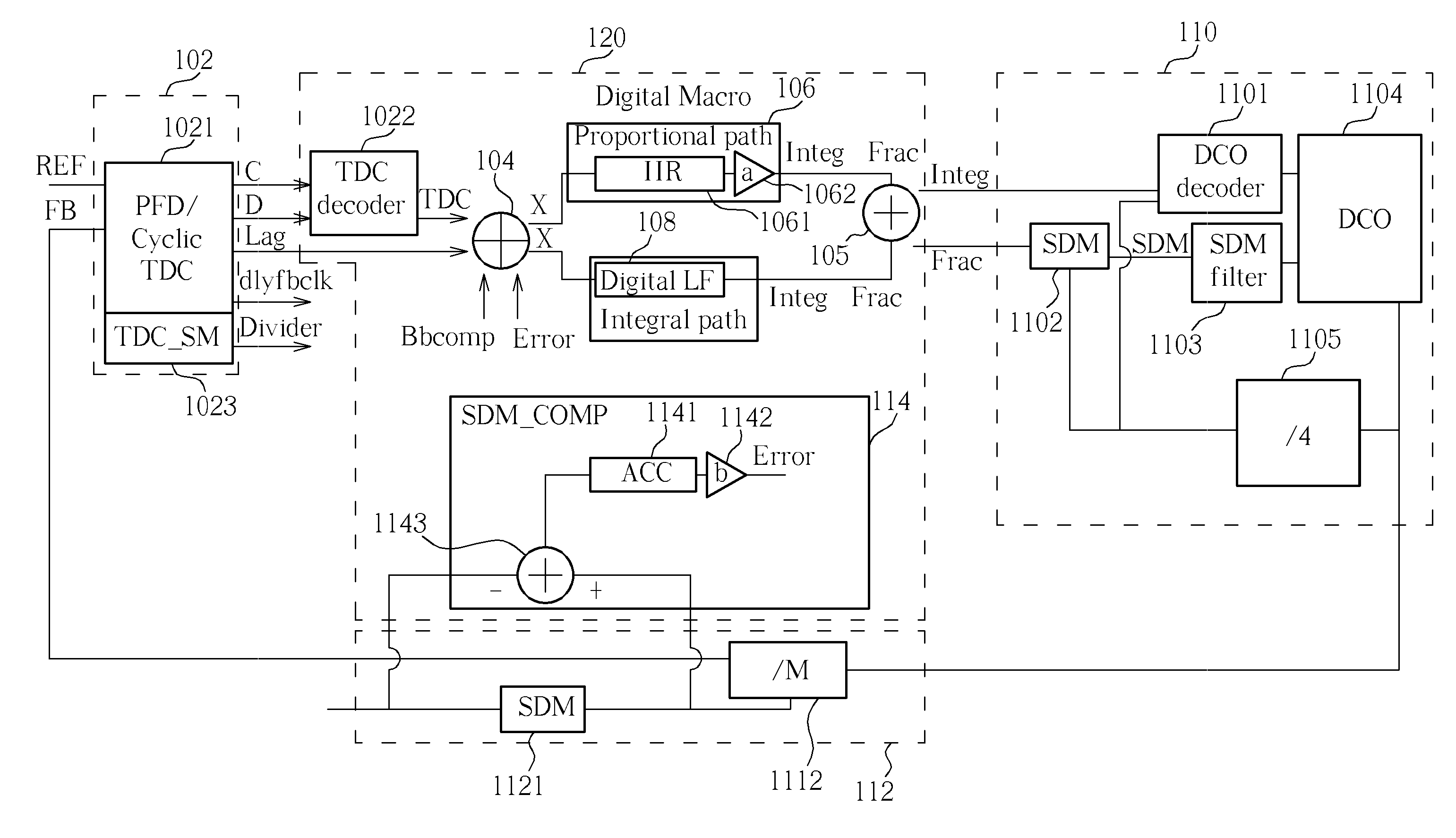
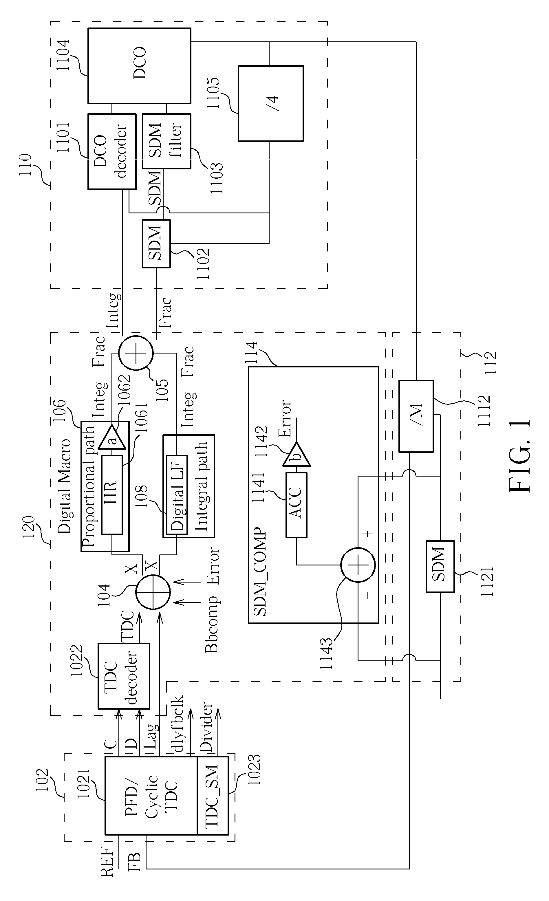
[0025]Please refer to FIG. 1, which is a diagram of an ADPLL 100 disclosed in the present invention. As shown in FIG. 1, ADPLL 100 includes a time-to-digital converter (TDC) module 102, a digital macro module 120, a digital-controlled oscillator (DCO) / sigma-delta modulator (SDM) module 110, and a feedback path module 112. The TDC module 102 includes a phase-frequency detector / cyclic time-to-digital converter (PFD / CTDC) module 1021 and a TDC state machine (TDC_SM) 1023. Though a cyclic TDC is employed in the embodiments hereinafter, any type of TDC may be applied to the invention. The digital macro module 120 includes a TDC decoder 1022, a first adder 104, a proportional path module 106, a digital low-pass filter (digital LF) 108, a second adder 105, and a SDM compensation module 114. The proportional path module 106 includes an infinite impulse response (IIR) module 1061 and a proportional path module (PPM) amplifier 1062. Note that a gain of the PPM amplifier 1062 is a. The digital...


PUM


Abstract

Phase error of a time-to-digital converter (TDC) within an all-digital phase-locked loop (ADPLL) is compensated by predicting possible phase error, which are predicted according to an estimated quantization error, a period of a digital-controlled oscillator (DCO), a gain of the TDC or a combination thereof. By appropriate inductions, the possible phase error may be further indicated by the quantization error, a code variance corresponding to a half of a reference period received by a TDC module having the TDC, a dividing ratio of a frequency divider of the ADPLL, a fractional number related to the quantization error o a combination thereof. A digital phase error cancellation module is also used for generating the possible phase error for compensating the phase error of the TDC.

Description

CROSS REFERENCE TO RELATED APPLICATIONS[0001]This application claims the priority of U.S. Provisional Applications No. 60 / 980,172, filed on Oct. 16, 2007 and 60 / 980,461, filed on Oct. 17, 2007, which is included herein by reference.Background of the Invention[0002]1. Field of the Invention[0003]The present invention relates to an error compensation method, a digital phase error cancellation, and an ADPLL (All-digital phase-locked loop) thereof, and more particularly, to an error compensation method for, a digital phase error cancellation module, and an ADPLL having the digital phase error cancellation module.[0004]2. Description of the Prior Art[0005]A phase-locked loop (PLL) is an electronic control system that generates a signal that has a fixed relation to the phase of a reference signal. A phase-locked loop circuit responds to both the frequency and the phase of the input signals, and automatically raises or lowers the frequency of a controlled oscillator until it is matched to ...

Claims


Application Information

Patent Timeline
Patent Type & Authority Applications(United States)
IPC IPC(8): H03D3/24
CPCH03L7/085H03L2207/50H03L7/0991
Inventor CHANG, HSIANG-HUIHSIEH, BING-YUZHAN, JING-HONG CONAN
Owner MEDIATEK INC
Why Eureka
Try Eureka