
Mixed-mode PLL

a mixed-mode, phase locked loop technology, applied in the direction of oscillator generators, pulse automatic control, angle modulation details, etc., can solve the problem of inability to eliminate fractional spurs, inability to achieve low dco quantization errors, and inability to filter to zero fractional spurs by digital lows. achieve the effect of improving the short-term frequency resolution of dco

Active Publication Date: 2011-10-04
MEDIATEK INC
View PDF8 Cites 8 Cited by
  • Summary
  • Abstract
  • Description
  • Claims
  • Application Information

AI Technical Summary

Benefits of technology

[0011]The invention provides a spur reduction technique to eliminate the fractional spur by improving the short-term frequency resolution of a DCO. The technique only requires adding a simple analog low pass filter and rearranging switches in the DCO used in the conventional ADPLL.

Problems solved by technology

The spur induced by the non-linearity can not be filtered to zero by a digital low pass filter or a digital algorithm because the resolution of the digital loop filter is finite, which is limited by the quantization errors of the DCO.
Although the noise induced by the quantization error is reduced using this technique, this technique cannot eliminate the fractional spur.
This is because the short-term DCO quantization error remains the output signal.
Additionally, it is impossible to achieve a low DCO quantization error since the required MOS capacitor geometry will be smaller than what an advanced process can provide.

Method used


Image

  • Mixed-mode PLL
  • Mixed-mode PLL
  • Mixed-mode PLL

Examples


Embodiment Construction

[0022]The following description is of the best-contemplated mode of carrying out the invention. This description is made for the purpose of illustrating the general principles of the invention and should not be taken in a limiting sense. The scope of the invention is best determined by reference to the appended claims.

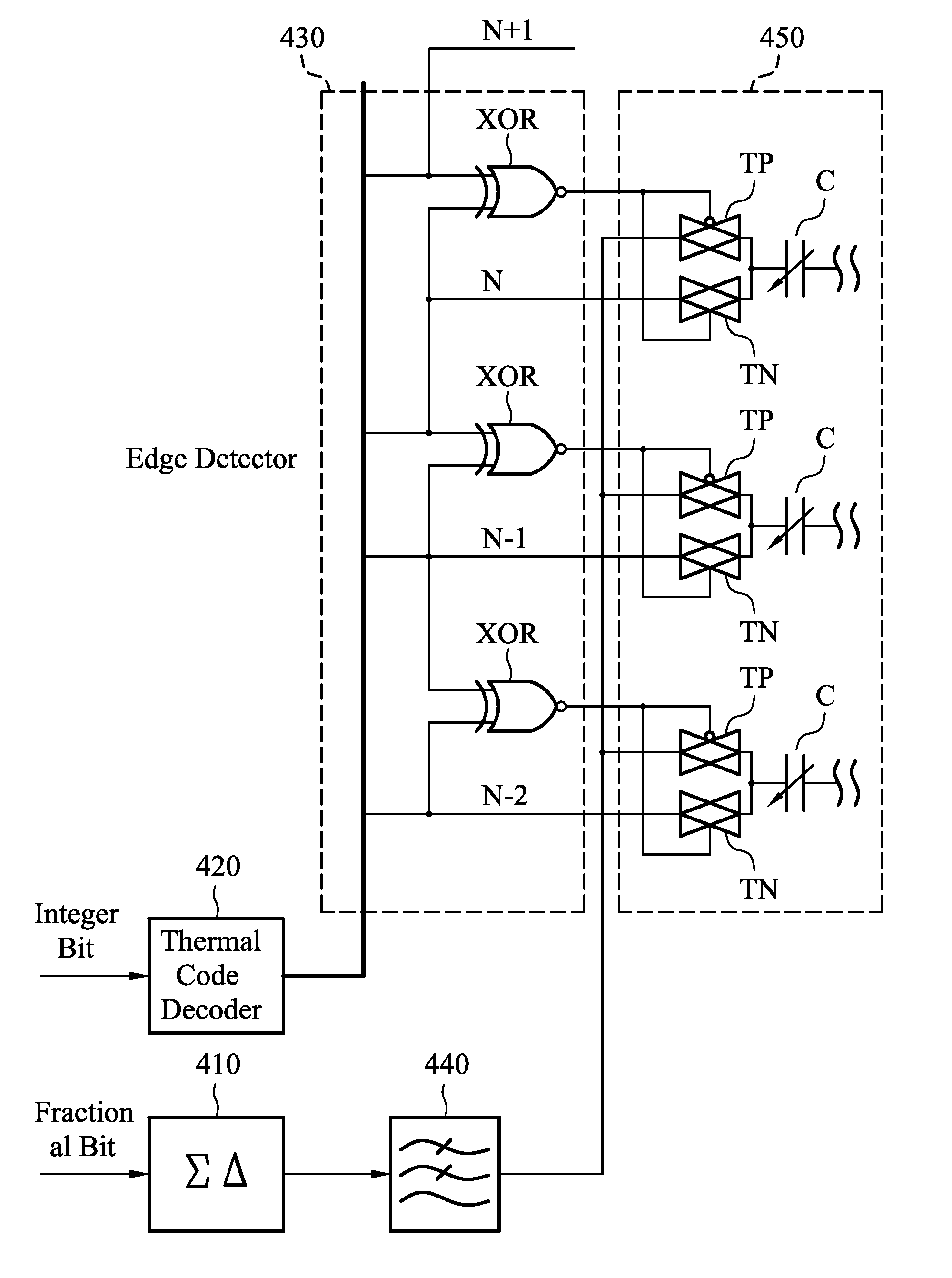
[0023]FIG. 4 is a schematic diagram showing part of a mixed-mode PLL according to an embodiment of the invention. In FIG. 4, the mixed-mode PLL comprises a digital sigma-delta modulator 410, a thermal code decoder 420, an edge detector 430, a low pass filter 440, and a digital controlled oscillator 450. The digital sigma-delta modulator 410 receives a fractional bit signal. The thermal decoder 420 receives an integer bit signal. The low pass filter 440 is coupled to the digital sigma-delta modulator 410. The low pass filter 440 receives an output signal of the digital sigma-delta modulator 410 and converts the output signal to an analog control signal. The digital cont...


PUM


Abstract

A mixed-mode PLL is disclosed. The mixed-mode PLL comprises a digital sigma-delta modulator, a low pass filter, and a digital controlled oscillator. The digital sigma-delta modulator receives a fractional bit signal. The low pass filter is coupled to the digital sigma-delta modulator. The low pass filter receives an output signal of the digital sigma-delta modulator and converts the output signal to an analog control signal. The digital controlled oscillator comprises a varactor dynamically coupled to the low pass filter and receiving the analog control signal.

Description

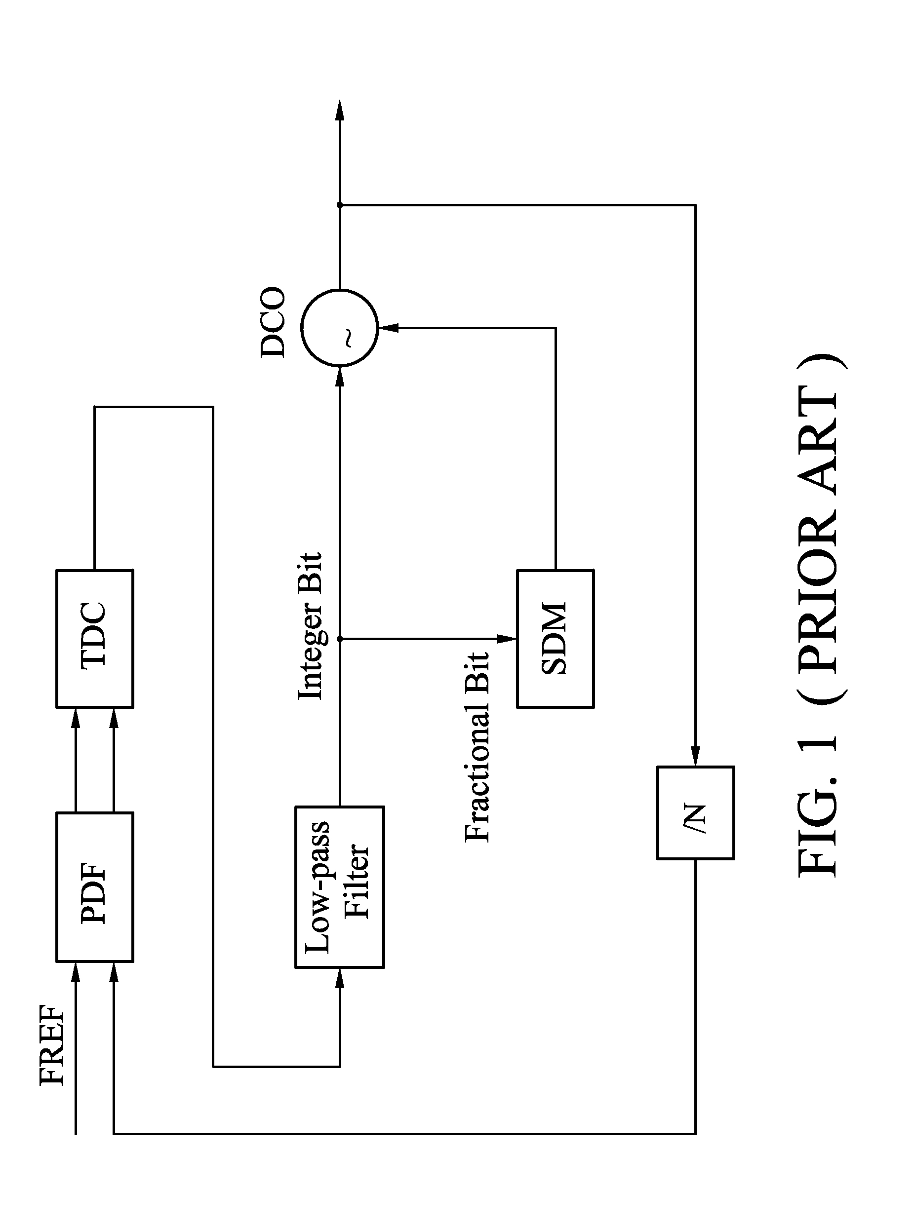
BACKGROUND OF THE INVENTION[0001]1. Field of the Invention[0002]The invention relates to an all digital phase locked loop (ADPLL) and, in particular, to a fractional spur reduction technique for an ADPLL.[0003]2. Description of the Related Art[0004]All digital phase locked loops (ADPLLs) have been reported to have superior performance with low cost. However, a fraction-N operation of an ADPLL induces high fractional spur as compared to a conventional charge pump-based fraction-N PLL, which is the most popular architecture used in wireless applications.[0005]In a conventional delta-sigma fractional PLL, the fractional spur is induced by non-linearity of the loop such as charge pump current mismatch and clock feed-through. However, the induced fractional spur can be suppressed to zero by a passive low pass filter to make circuit design more robust. On the other hand, for an all-digital PLL (ADPLL) as shown in FIG. 1, non-linearity of the loop is induced by quantization errors / non-line...

Claims


Application Information

Patent Timeline
Patent Type & Authority Patents(United States)
IPC IPC(8): H03L7/085H03C3/22
CPCH03L7/099H03L7/16
Inventor WANG, PING-YINGCHANG, HSIANG-HUI
Owner MEDIATEK INC
Learn More