All-digital sub-sampling phase-locked loop and frequency range locking method thereof

A sub-sampling, phase-locked loop technology, applied in the field of all-digital sub-sampling phase-locked loop and its frequency range locking, can solve the problems of small frequency locking range and large power consumption of auxiliary circuits, and achieve extended frequency locking range and hardware overhead. The effect of small, efficient loop control

Active Publication Date: 2020-01-17
FUDAN UNIV
View PDF11 Cites 6 Cited by
  • Summary
  • Abstract
  • Description
  • Claims
  • Application Information

AI Technical Summary

Problems solved by technology

This system and method aims to solve the problems of small frequency locking range of traditional sub-sampling phase-locked loops and large power consumption of frequency-locking auxiliary circuits. The working state of the sub-sampling phase detector is determined by an all-digital mode switcher, and the output mode is switched, so that The phase-locked loop can still work correctly when there is a large frequency error and the auxiliary frequency locking circuit is turned off, and the frequency locking range is expanded

Method used


Image

  • All-digital sub-sampling phase-locked loop and frequency range locking method thereof
  • All-digital sub-sampling phase-locked loop and frequency range locking method thereof
  • All-digital sub-sampling phase-locked loop and frequency range locking method thereof

Examples


Embodiment Construction

[0065] The present invention will be further described below through specific embodiments in conjunction with the accompanying drawings. These embodiments are only used to illustrate the present invention, and are not intended to limit the protection scope of the present invention.

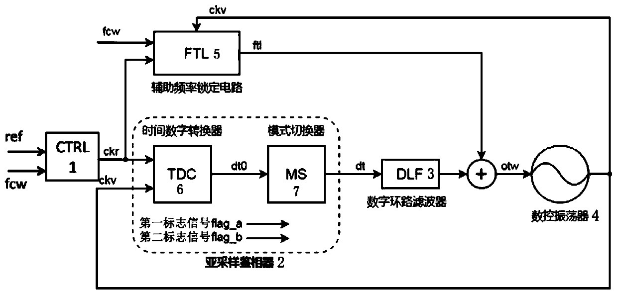
[0066] The present invention is an all-digital sub-sampling phase-locked loop, such as figure 1 As shown, including clock generation and control circuit 1 (CTRL), sub-sampling phase detector 2 (SSPD), digital loop filter 3 (DLF), numerically controlled oscillator 4 (DCO) and auxiliary frequency locking circuit 5 (FTL) .

[0067] The clock generation and control circuit 1 performs phase calculation according to the reference frequency ref set by the PLL and the control frequency signal fcw, and outputs the low frequency control signal ckr.

[0068] The first input end of the sub-sampling phase detector 2 is connected to the first output end of the clock generation and control circuit 1 for sub-sam...


PUM


Abstract

The invention discloses an all-digital sub-sampling phase-locked loop and a frequency range locking method thereof. The all-digital sub-sampling phase-locked loop comprises a clock generation and control circuit; a sub-sampling phase discriminator the first input end of whichis connected with the first output end of the clock generation and control circuit; a digital loop filter the input end of whichis connected with the output end of the sub-sampling phase discriminator; a numerical control oscillator the first input end of whichis connected with the output end of the digital loop filter, and the first output end of which is connected with the second input end of the sub-sampling phase discriminator; and the first input end of the auxiliary frequency locking circuit is connected with thesecond output end of the clock generation and control circuit, the second input end is connected with the second output end of the numerical control oscillator, and the output end is connected with the second input end of the numerical control oscillator. The problems that a traditional sub-sampling phase-locked loop is small in frequency locking range and a frequency locking auxiliary circuit islarge in power consumption are solved, the output mode of the sub-sampling phase discriminator is judged and switched through the all-digital mode switcher, and the frequency locking range is expanded.

Description

technical field [0001] The invention relates to the technical field of integrated circuits, in particular to an all-digital sub-sampling phase-locked loop and a frequency range locking method thereof. Background technique [0002] The all-digital phase-locked loop uses digital circuits to realize loop control, so it has a high degree of design and implementation flexibility, is easy to integrate with other on-chip systems, and can achieve better performance with the development of integrated circuit manufacturing processes, so it has a very wide range of applications. application. [0003] In the all-digital phase-locked loop, the sub-sampling loop structure is adopted. Under the control of the low-frequency reference clock, the high-frequency output of the oscillator is directly sampled to obtain phase error information, and then the output of the oscillator is adjusted through negative feedback control. Frequency, to achieve the function of the phase-locked loop. Since t...

Claims


Application Information

Patent Timeline
Patent Type & Authority Applications(China)
IPC IPC(8): H03L7/087H03L7/089H03L7/091
CPCH03L7/087H03L7/0898H03L7/091
Inventor 徐荣金叶大蔚史传进
Owner FUDAN UNIV
Why Eureka
Try Eureka