
Clock synthesizer with integral non-linear interpolation (INL) distortion compensation

a clock synthesizer and non-linear interpolation technology, applied in the field of precision timing, can solve the problems of imperfect linear dtc, which is implemented in analog form, and achieve the effect of accurate compensation method, low jitter output clock, and rapid and adaptive adjustment of non-linear distortion

Active Publication Date: 2018-11-13
MICROSEMI SEMICON
View PDF1 Cites 8 Cited by
  • Summary
  • Abstract
  • Description
  • Claims
  • Application Information

AI Technical Summary

Benefits of technology

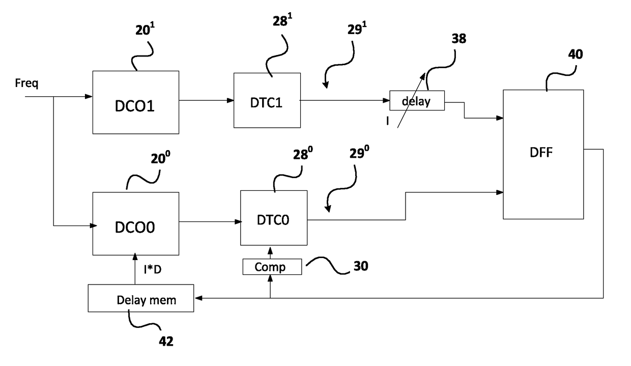
The invention describes a method to create a low jitter output clock by compensating for non-linear distortion in DTC interpolation. The method uses two paths, each containing a DCO and a DTC, and introduces a deliberate initial delay in one path to match the output of the other path. By averaging measurements for multiple matching pairs of initial and compensating delays, the invention produces discrete average non-linear distortion values for each interpolation point in the first path and an average non-linear distortion value for all M interpolation points over a system clock period in the second path. This average is treated as a constant and can be allowed for in the final circuitry. The technical effect of the invention is a more accurate compensation for non-linear distortion in DTC interpolation, resulting in a lower jitter output clock.

Problems solved by technology

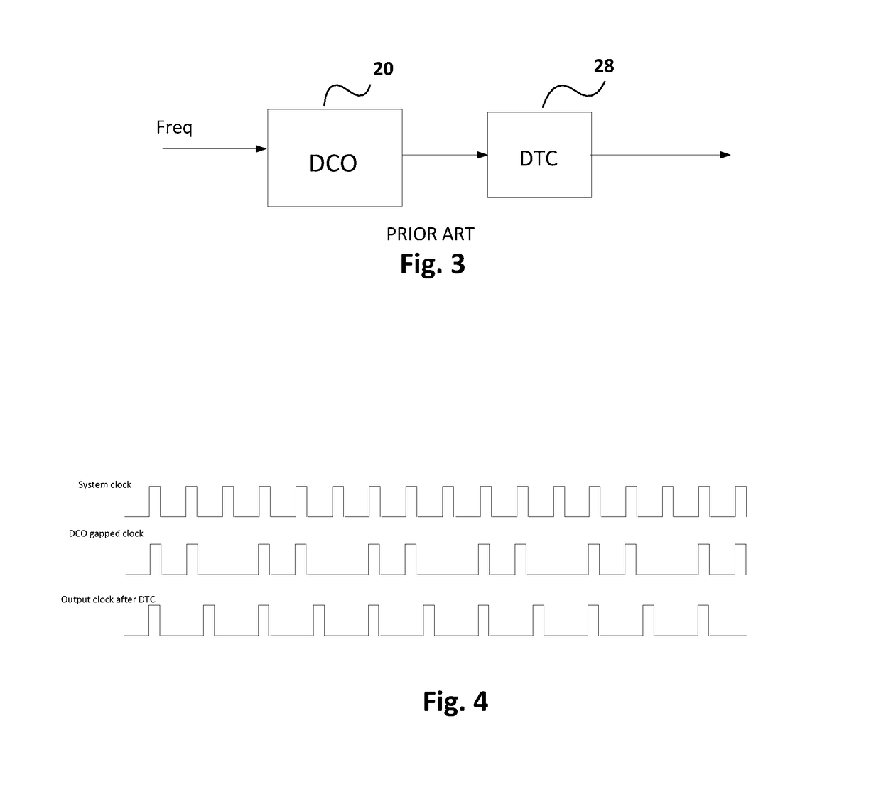
The DCO produces clock pulses at the desired overall frequency, but since these pulses are coincident with the system pulses when the carry occurs, they are not generally correctly phased and form a so-called gapped clock signal because when there is no carry no output occurs on some of the system clock pulses.
A problem arises in the prior art due to the fact that the DTC, which is implemented in analog form, is not perfectly linear.

Method used


Image

  • Clock synthesizer with integral non-linear interpolation (INL) distortion compensation
  • Clock synthesizer with integral non-linear interpolation (INL) distortion compensation
  • Clock synthesizer with integral non-linear interpolation (INL) distortion compensation

Examples


Embodiment Construction

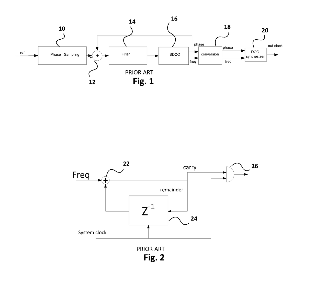
[0043]The phase locked loop (PLL) shown in FIG. 1 comprises a phase sampler 10 that samples the phase of a reference signal to produce samples that are applied to the plus input of adder 12, the output of which adder 12 is coupled to loop filter 14, which in turn provides the input to SDCO 16 (Software Digitally Controlled Oscillator). The SDCO 16 outputs phase and frequency values that are applied to a converter 18, which provides corresponding inputs to digital or numerically controlled (DCO) synthesizer 20. The phase output of the SDCO 16 is also fed back to the minus input of the adder so that the output of the PLL is locked to the reference signal. It will be appreciated that component 12 is shown as an adder, as is conventional, but when it adds a negative input to a positive input, it is of course acting as a subtractor.

[0044]The DCO 20 is shown in more detail in FIG. 2. It comprises an accumulator consisting of adder 22, a delay-by-one sample unit 24, and an AND gate 26. The...


PUM


Abstract

A method of compensating for integral nonlinear interpolation (INL) distortion in a clock synthesizer driven by a system clock running at a frequency fsys, involves introducing a selected nominal analog delay I*dt with an actual delay of I*dt+δ at the output of the a first path with a digital controlled oscillator (DCO) and a digital-to-time converter (DTC) and a nominal digital delay I*D with an actual delay of I*D+Δ at the input of a second path with a DCO and a DTC that offsets the actual analog delay in the first path, adjusting the contents x(k) of a compensation module in the second path to align the output pulses of the first and second paths for different values of k, where k represents an interpolation point, iteratively repeating the two preceding steps for all N values of I, and averaging the contents x(k) of the compensation module to derive the compensation values to be applied to a one of the DTCs to correct for INL distortion.

Description

CROSS REFERENCE TO RELATED APPLICATION[0001]This application claims the benefit under 35 USC 119(e) of U.S. provisional application No. 62 / 447,583, filed, Jan. 18, 2017, the contents of which are herein incorporated by reference.FIELD OF THE INVENTION[0002]This invention relates to the field of precision timing, and in particular to a method of compensating for non-linear effects during phase interpolation in digital-to-time conversion, and a clock synthesizer for implementing the method.BACKGROUND OF THE INVENTION[0003]A variety of electronic circuits require the synthesis of extremely accurate clock signals at a precise frequency. One way of achieving this result is to lock a digital phase-locked loop employing a software digital controlled oscillator (SDCO) to generate phase and frequency values from a reference signal, which after suitable conversion, drive a hardware digital or numerical controlled oscillator (DCO / NCO), referred to hereafter as a DCO. This comprises an accumula...

Claims


Application Information

Patent Timeline
Patent Type & Authority Patents(United States)
IPC IPC(8): H03B21/00H03K5/1252H03L7/099H03L7/091H03K5/00
CPCH03K5/1252H03L7/091H03L7/0991H03L2207/50H03K2005/00052H03K2005/00058
Inventor JIN, QU GARYRAHBAR, KAMRAN
Owner MICROSEMI SEMICON
Learn More