Methods to reconfigure all-fiber optical cross-connects

a technology of fiber optic cross-connect and reconfiguration process, which is applied in the direction of optical elements, multiplex communication, instruments, etc., can solve the problems of limited optical performance and scalability, difficult task of allocating, reconfiguring and testing a fiber circuit within the network, and substantial alignment complexity, so as to achieve high reliability operation and the effect of adjusting the reconfiguration process

Active Publication Date: 2009-04-16
TELESCENT
View PDF7 Cites 35 Cited by
  • Summary
  • Abstract
  • Description
  • Claims
  • Application Information

AI Technical Summary

Benefits of technology

[0017]Methods in accordance with the invention reposition fiber optic lines between the discrete elements in a first array that is two-dimensional in character and spaced apart collection lines in a linear array in a second plane parallel to the first. The method maintains an updated inventory of the interconnections and utilizes the lookup of this inventory to direct a positioner for engaging and disengaging fiber optic connections from the first array through columnar interstices between the connector elements in the first array. In response to a command to locate and move a selected line engaged in the first array, the positioner is driven along the interstices between columns and across rows to the selected location. Then under deterministic operating rules consistent with the known arrangement of interconnection vectors, the positioner and line are moved along the columnar interstices from one column to another until the target location is reached. A particularly advantageous method in accordance with the invention temporarily stores the connectors out of the path of the existing vector inventory. Further the rows of connectors are shifted incrementally in timed relation to the columnar motions. Thus the line being repositioned in vicinity of the first plane can be interwoven above existing lines whose vectors terminate at lower elevations at the second plane, and below existing lines whose vectors terminate at higher elevations at the second plane. Methods are further disclosed to augment the reconfiguration process with health monitoring processes such as optical power detection and electrical continuity detection to achieve high reliability operation.

Problems solved by technology

Consequently, the tasks of allocating, reconfiguring and testing a fiber circuit within the network is challenging because of the potential for errors or damage resulting from manual intervention.
Non-robotic cross-connect switches, while offering the potential for relatively high speed (10 ms), do so at the expense of limited optical performance and scalability.
The coupling of light into and out-of fiber and free-space introduces substantial alignment complexity and significantly increases insertion loss, back reflection and crosstalk.
As a consequence, MEMS switches do not provide an optically transparent, plug-and-play replacement for manual fiber optic patch-panels.
However, the scalability of such approaches has been limited.
Robotic and non-robotic approaches have not been modular and as such, they do not offer an upgrade path from 200 ports to 1000 ports, for example.
406-424 (1953)], leading to a substantial increase in cost, complexity and a reduction in optical performance by virtue of the need to transmit through a series arrangement of three rather than one switch element.
In addition, the optical performance of robotic cross-connects, while improving on non-robotic approaches, is still inferior to manual patch-panels because they introduce an additional fiber optic connection in series with each fiber circuit.
These fiber end faces physically contact one another and can exhibit wear-out for switch cycles in excess of 1000, or can become damaged at the high optical power levels transmitted through fiber in Raman amplified systems.
The performance of frequently reconfigured test ports is therefore susceptible to degradation.
The robotic cross-connect approaches described in the prior art have limited scalability and optical performance.

Method used


Image

  • Methods to reconfigure all-fiber optical cross-connects
  • Methods to reconfigure all-fiber optical cross-connects
  • Methods to reconfigure all-fiber optical cross-connects

Examples


Embodiment Construction

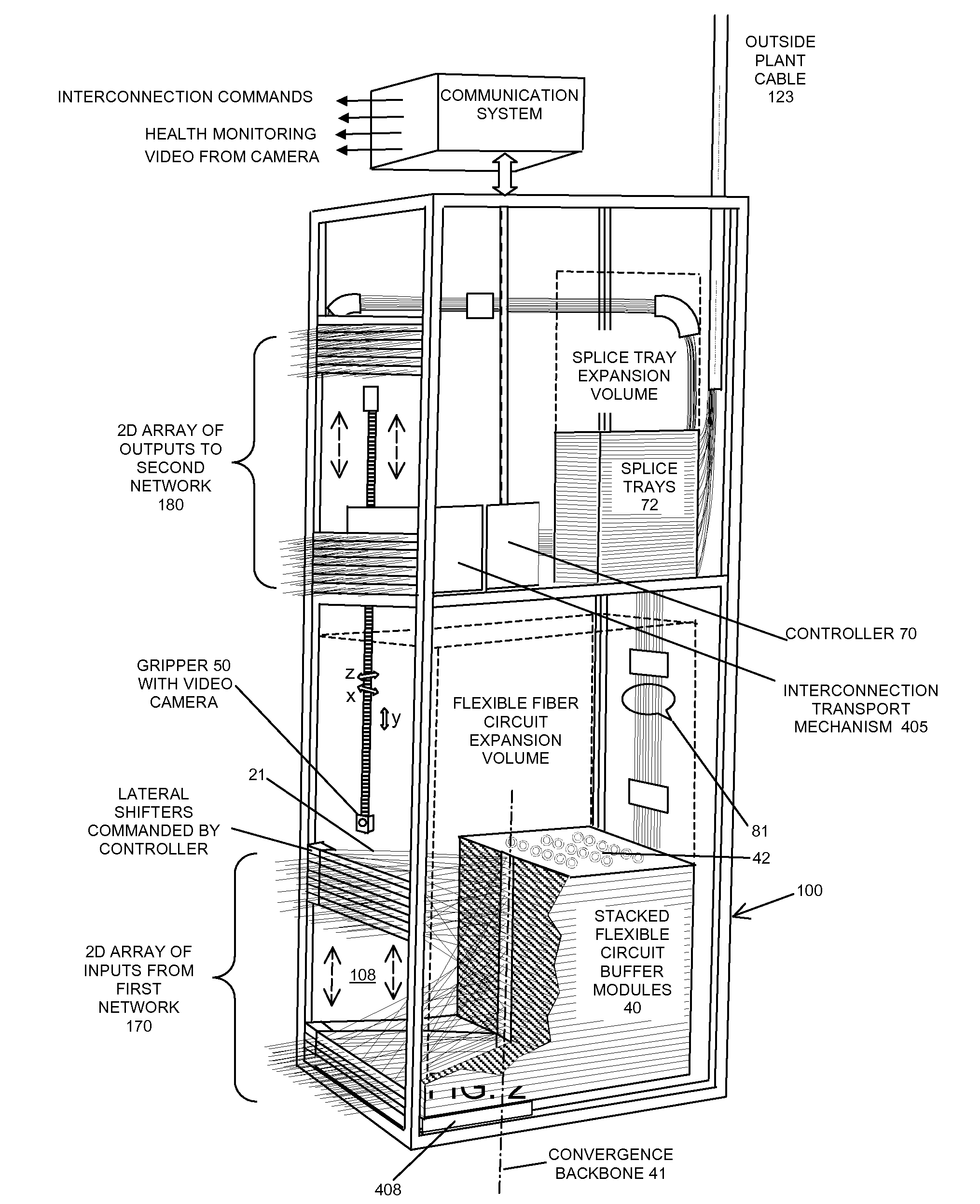
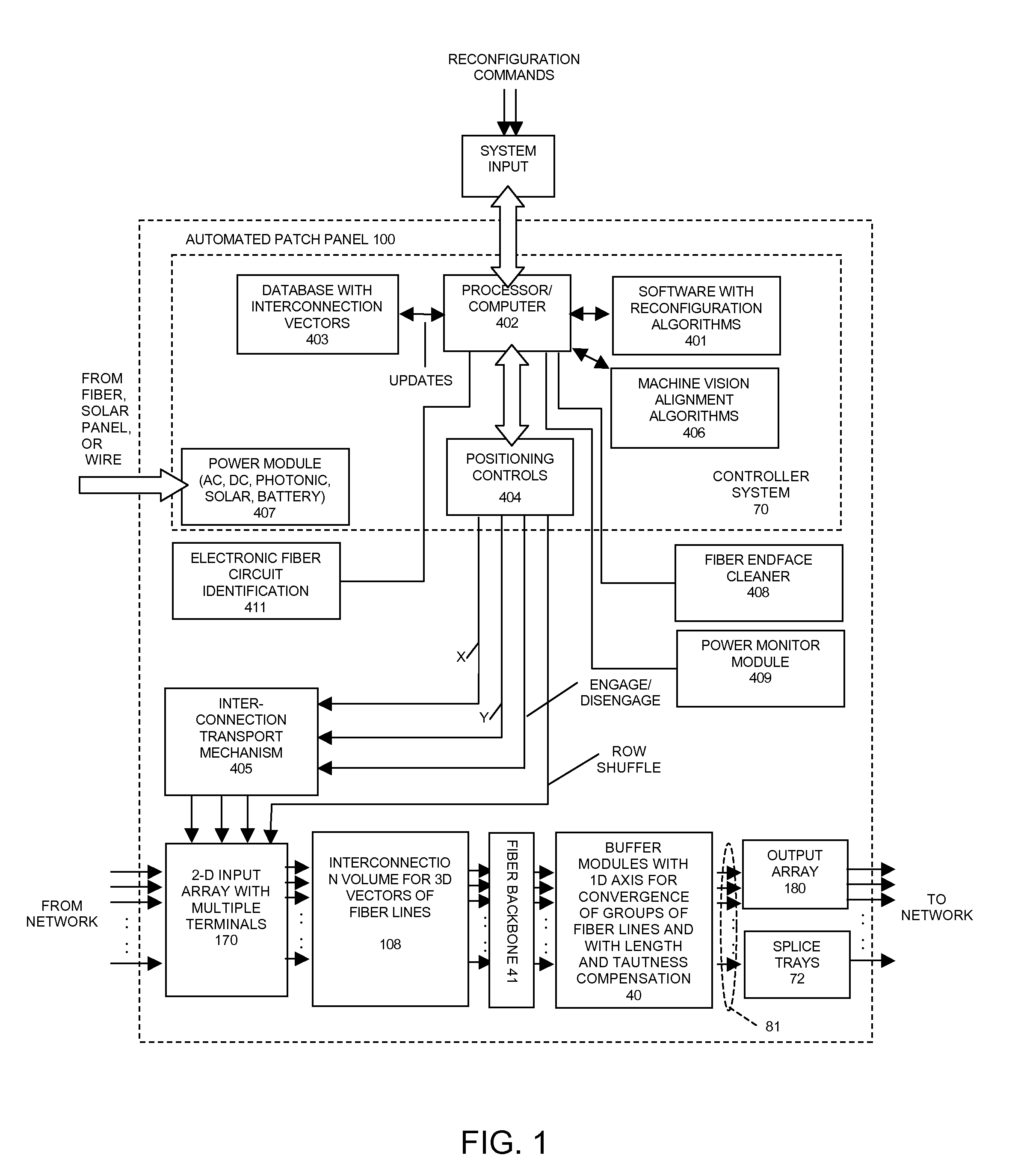
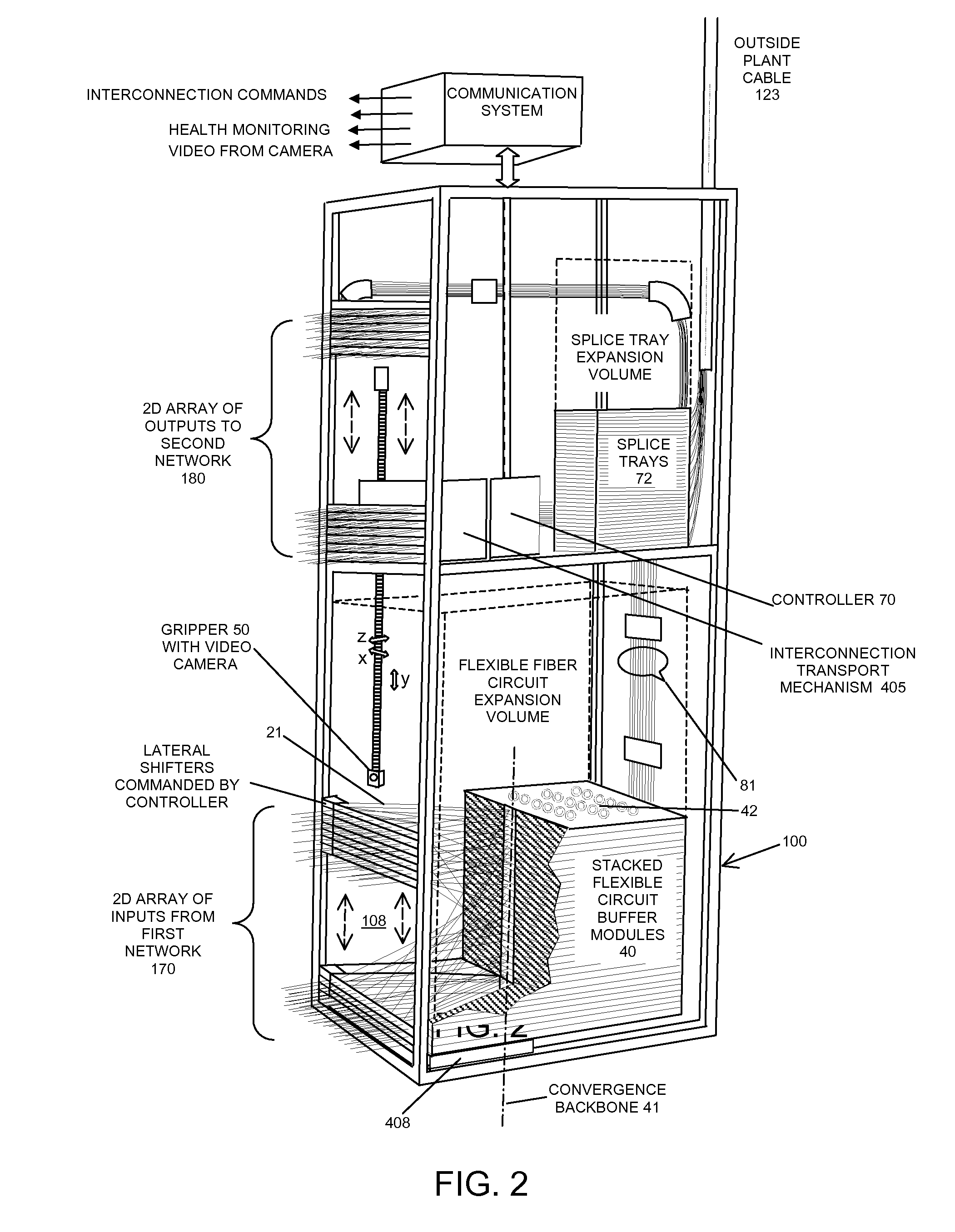
[0032]In this invention, we disclose methods to reconfigure all-fiber cross-connect switching systems such as those illustrated in block diagram view in FIG. 1 and in partial cutaway, perspective view in FIG. 2. These systems are comprised of 100's to 1000's of fiber interconnects suspended between two planes and intermixing within a common volume. Reconfigurable fiber connections are made internal to this volume, between a two-dimensional array of reconfigurable input terminals 170 and an intermediate, substantially one-dimensional array 41 bounding the interconnect volume 108. The suspended fiber lines 21 therebetween follow substantially straight-line paths and define a three-dimensional arrangement of vectors directed towards the one-dimensional array 41 located at an intermediate plane, beyond which the fiber lines 21 exit contiguously to a modular arrangement of substantially identical, stacked buffer elements 40. Buffer elements provide slight tensioning, parallel to vectors ...


PUM


Abstract

This invention discloses methods to reconfigure highly scalable and modular automated optical cross connect switch devices comprised of large numbers of densely packed fiber strands suspended within a common volume. In particular, methods enabling programmable interconnection of large numbers of optical fibers (100's-1000's) are provided, whereby a two-dimensional input array of fiber optic connections is mapped in an ordered and rule-based fashion into a one-dimensional array. A particular algorithmic implementation for a system reconfigured by a three-axis robotic gripper as well as lateral translation of each row in the input port array is disclosed.

Description

REFERENCE TO RELATED APPLICATIONS[0001]This application is based on provisional patent application 60 / 980,148 filed on Oct. 15, 2007 and entitled “Fiber Optic Cross Connect Switch Using Flexible, Planar Fiber Optic Circuits”, provisional patent application 60 / 987,414 filed on Nov. 13, 2007 and entitled “Fiber Optic Cross Connect Switch Using Layered Fiber Optic Circuits”, provisional patent application 61 / 016,794 filed on Dec. 26, 2007 and entitled “Automated Fiber Optic Patch-Panels Using Flexible Fiber Optic Circuits”, provisional patent application 61 / 018,668 filed on Jan. 2, 2008 and entitled “Large Scale Optical Cross-Connect Switch”, provisional patent application 61 / 038,777 filed on Mar. 24, 2008 and entitled “Scalable and Modular Automated Fiber Optic Cross-Connect” and provisional patent application 61 / 078,396 filed on Jul. 6, 2008 and entitled “Methods to Reconfigure All-Fiber Optical Cross-Connects”.[0002]This application is filed concurrently with application Ser. No. __...

Claims


Application Information

Patent Timeline
Patent Type & Authority Applications(United States)
IPC IPC(8): G02B6/26
CPCG02B6/3502G02B6/3556H04Q11/0005G02B6/3564H04Q1/145G02B6/356G02B6/3897G02B6/4452H04Q2011/0058
Inventor KEWITSCH, ANTHONY
Owner TELESCENT
Why Eureka
Try Eureka