Optical receiving device and optical transmission system

a technology of optical transmission system and optical receiving device, which is applied in the direction of transmission monitoring, multiplex communication, wavelength-division multiplex system, etc., can solve the problems of affecting the transmission capacity, and affecting the transmission system

Inactive Publication Date: 2009-04-16
FUJITSU LTD
View PDF7 Cites 13 Cited by
  • Summary
  • Abstract
  • Description
  • Claims
  • Application Information

AI Technical Summary

Problems solved by technology

When pulse broadening due to chromatic dispersion occurs in a WDM system, which is for implementing a large capacity optical transmission for a long distance, it damages the system, significantly degrading the receiving capability.
As a WDM transmission system, however, usually manages the dispersion compensation of a central wavelength of multiplexed wavelengths so as to make a dispersion amount zero, it cannot compensate for the dispersion of signals whose wavelengths are other than the central wavelength, leaving the dispersion accumulated at a receiver side.
If a chromatic dispersion amount deviates from the dispersion tolerance, the receiving side cannot guarantee its ability to distinguish between the signals “0” and “1” (eye-opening degradation becomes too severe to distinguish data).

Method used


Image

  • Optical receiving device and optical transmission system
  • Optical receiving device and optical transmission system
  • Optical receiving device and optical transmission system

Examples


first embodiment

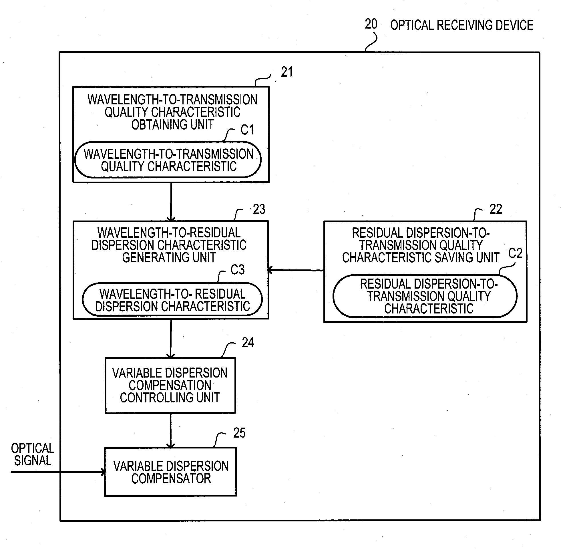
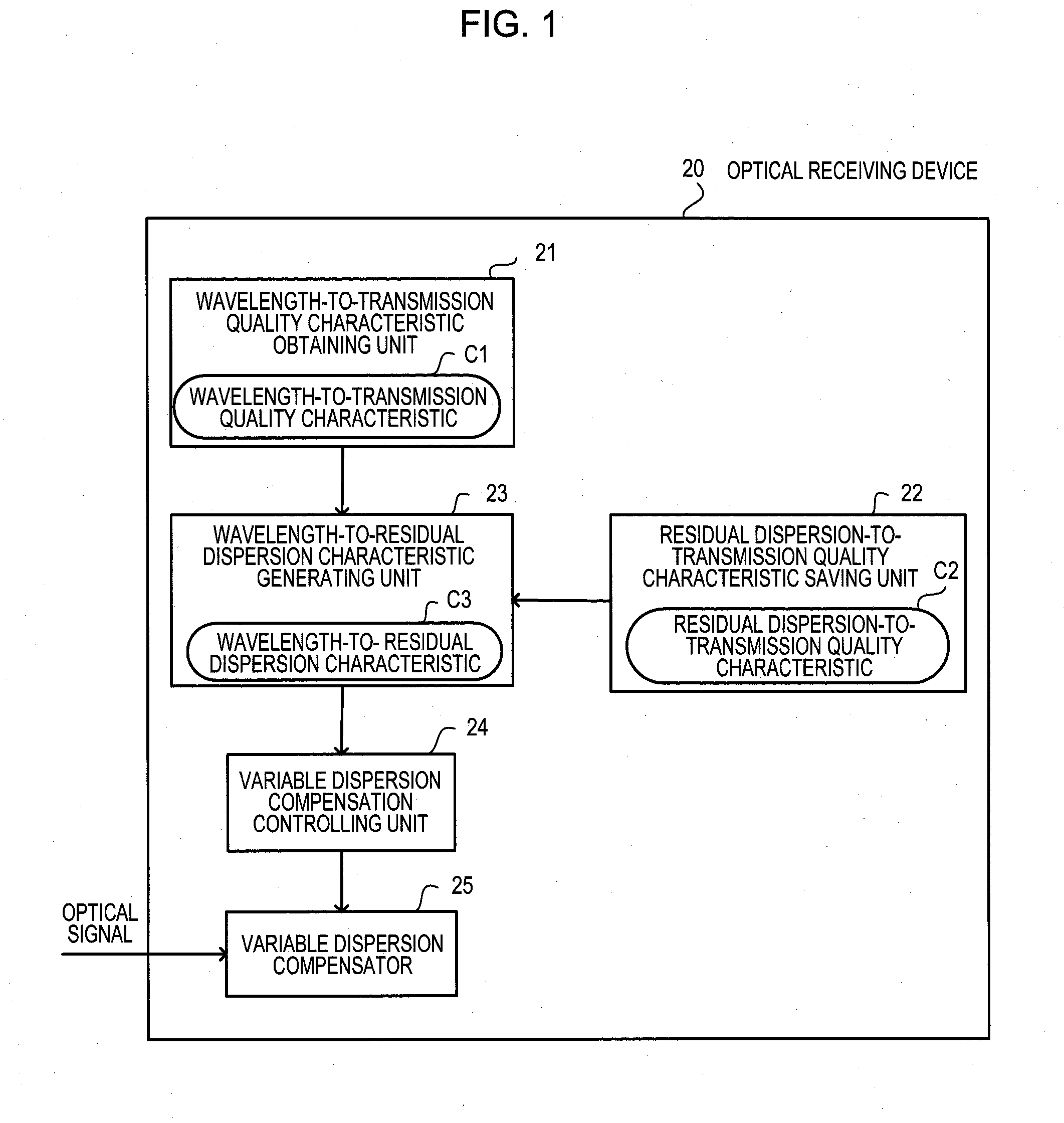
[0052]Embodiments will be described below with reference to the drawings. FIG. 1 illustrates an outline of an optical receiving device. An optical receiving device 20 of a first embodiment is a device for making an optical receiving process by providing dispersion compensation on a WDM signal. The optical receiving device 20 is composed of a wavelength-to-transmission quality characteristic obtaining unit 21, a residual dispersion-to-transmission quality characteristic saving unit 22, a wavelength-to-residual dispersion characteristic generating unit 23, a variable dispersion compensation controlling unit 24, and a variable dispersion compensator 25.

[0053]The wavelength-to-transmission quality characteristic obtaining unit 21 obtains a wavelength-to-transmission quality characteristic C1 that represents a relationship between wavelengths of low speed channels and transmission qualities that are actually measured for the respective wavelengths of the low speed channels by measuring t...

second embodiment

[0096]In contrast, in the second embodiment, it is assumed that a plurality of high speed channels are introduced on the system when low speed channels are replaced by high speed channels. The embodiment is adapted to obtain a dispersion compensation amount of the new high speed channel from information on dispersion compensation amounts set in the already installed variable dispersion compensator.

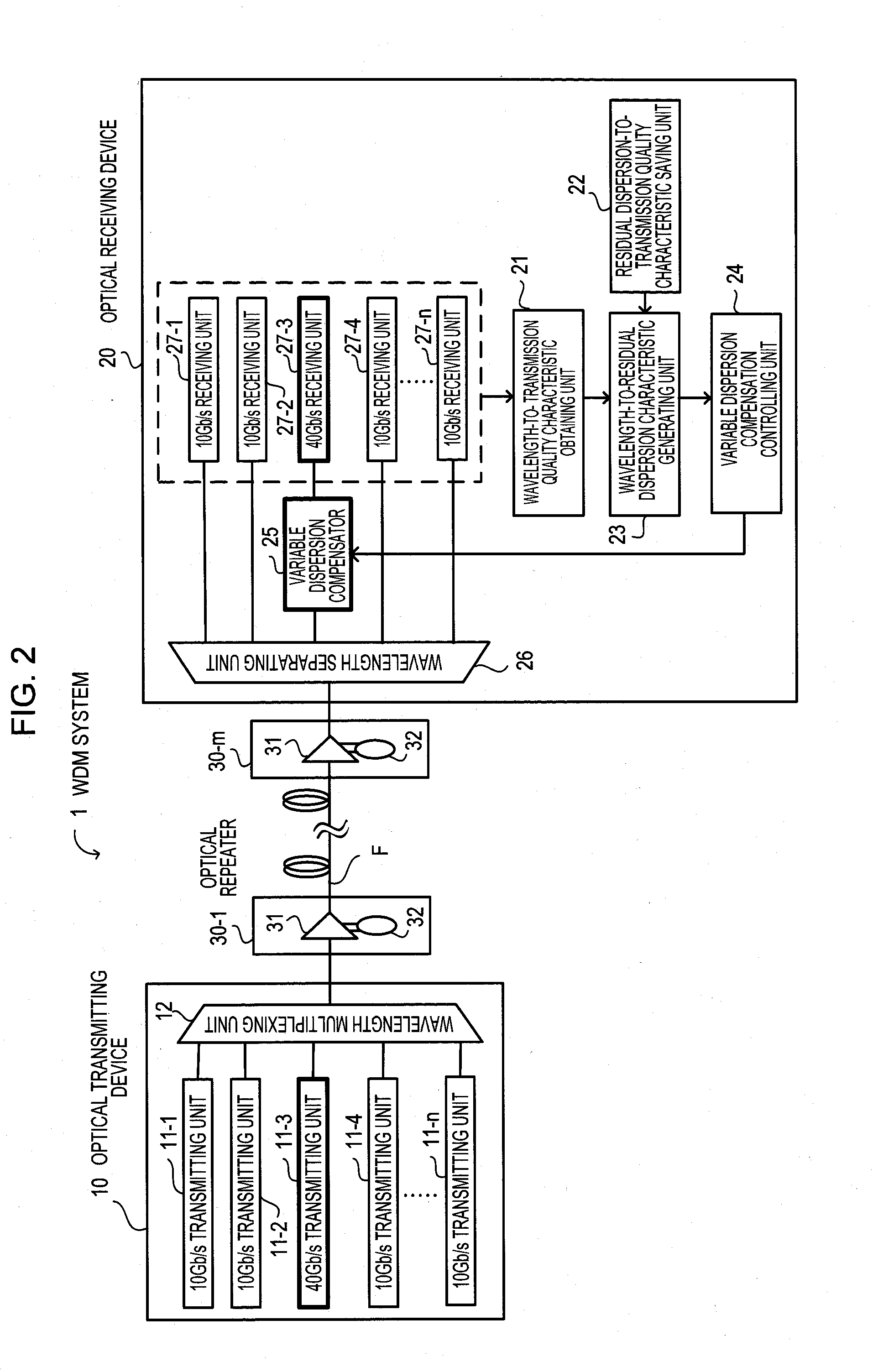
[0097]FIG. 7 illustrates a configuration of a WDM system. A WDM system 1a is composed of an optical transmitting device 10a, an optical receiving device 40, and optical repeaters 30-1 to 30-m. The optical transmitting device 10a and the optical receiving device 40 are connected with each other by an optical fiber transmission line F. The optical repeaters 30-1 to 30-m are arranged on the optical fiber transmission line F.

[0098]FIG. 7 illustrates a WDM system where WDM transmission is conducted in a mixed state of channels where the first channel and the nth channel are 40 Gb / s channels and...


PUM


Abstract

According to an aspect of an embodiment, an apparatus includes: a wavelength-to-transmission quality characteristic obtaining unit for obtaining a wavelength-to-transmission quality characteristic; a residual dispersion-to-transmission quality characteristic saving unit for saving a residual dispersion-to-transmission quality characteristic; a wavelength-to-residual dispersion characteristic generating unit for generating a wavelength-to-residual dispersion characteristic from a relationship between the wavelengths of the other channels and the residual dispersion based on the wavelength-to-transmission quality characteristic and the residual dispersion-to-transmission quality characteristic; a variable dispersion compensator for providing variable dispersion compensation to another channel,; and a variable dispersion compensation controlling unit for performing setting control on a dispersion compensation amount.

Description

CROSS-REFERENCE TO RELATED APPLICATIONS[0001]This application is based upon and claims the benefit of priority from the prior Japanese Patent Application No. 2007-266306, filed on Oct. 12, 2007, the entire contents of which are incorporated herein by reference.BACKGROUND[0002]1. Field[0003]The present application relates to an optical receiving device and an optical transmission system, for example.[0004]2. Description of the Related Art[0005]Recently, as the growth of broadband services has boosted a demand for communications, the demand for increasing the capacity of a backbone transmission system of an optical communication network has been rising. Under such circumstances, a WDM transmission system of 40 Gb / s has been gradually commercialized.[0006]There are two ways to put a WDM transmission system of 40 Gb / s into use: replacing all low speed channels of 10 Gb / s or the like by high speed channels of 40 Gb / s; and replacing some low speed channels of an existing network by high s...

Claims


Application Information

Patent Timeline
Patent Type & Authority Applications(United States)
IPC IPC(8): H04B10/06H04B10/2507H04B10/07H04B10/2525H04B10/291H04B10/524H04B10/58H04J14/00H04J14/02
CPCH04B10/66H04B10/2513
Inventor NAKAMURA, KENTARO
Owner FUJITSU LTD
Why Eureka
Try Eureka