Multiphase screw pump

a screw pump and multi-phase technology, applied in the direction of rotary/oscillating piston pump components, machines/engines, liquid fuel engines, etc., can solve the problems of easy failure of shaft seals and problematic use of shaft seals

Inactive Publication Date: 2009-04-16
GENERAL ELECTRIC CO
View PDF16 Cites 38 Cited by
  • Summary
  • Abstract
  • Description
  • Claims
  • Application Information

AI Technical Summary

Benefits of technology

[0008]In accordance with another exemplary embodiment disclosed herein, a system configured to transfer a process fluid medium is provided. The system includes a pump coupled to a motor and configured to be driven by the motor. The pump includes a pair of rotors disposed inside a casing having an inlet and an outlet. Each rotor includes a set of threads disposed on a portion of an outer surface of a shaft. A first bearing is coupled at a first end of the shaft, and a second bearing is coupled at a second end of the shaft. A single seal is coupled to a shaft of one of the rotors. The seal is configured between the motor and the pump to allow the motor to utilize a clean fluid for its purposes without contamination from the process fluids. This allows for a more conventional motor design and modular implementation.

Problems solved by technology

The usage of shaft seals is problematic for several reasons.
The shaft seals are prone to failure.

Method used


Image

  • Multiphase screw pump
  • Multiphase screw pump
  • Multiphase screw pump

Examples


Embodiment Construction

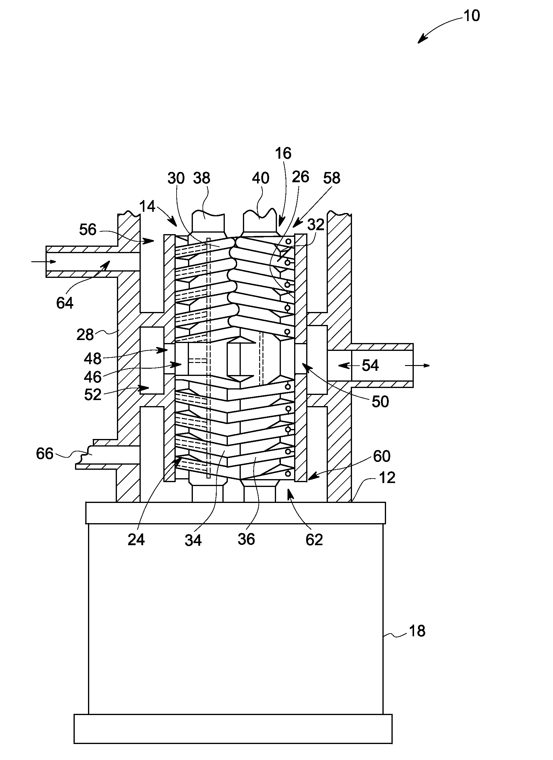
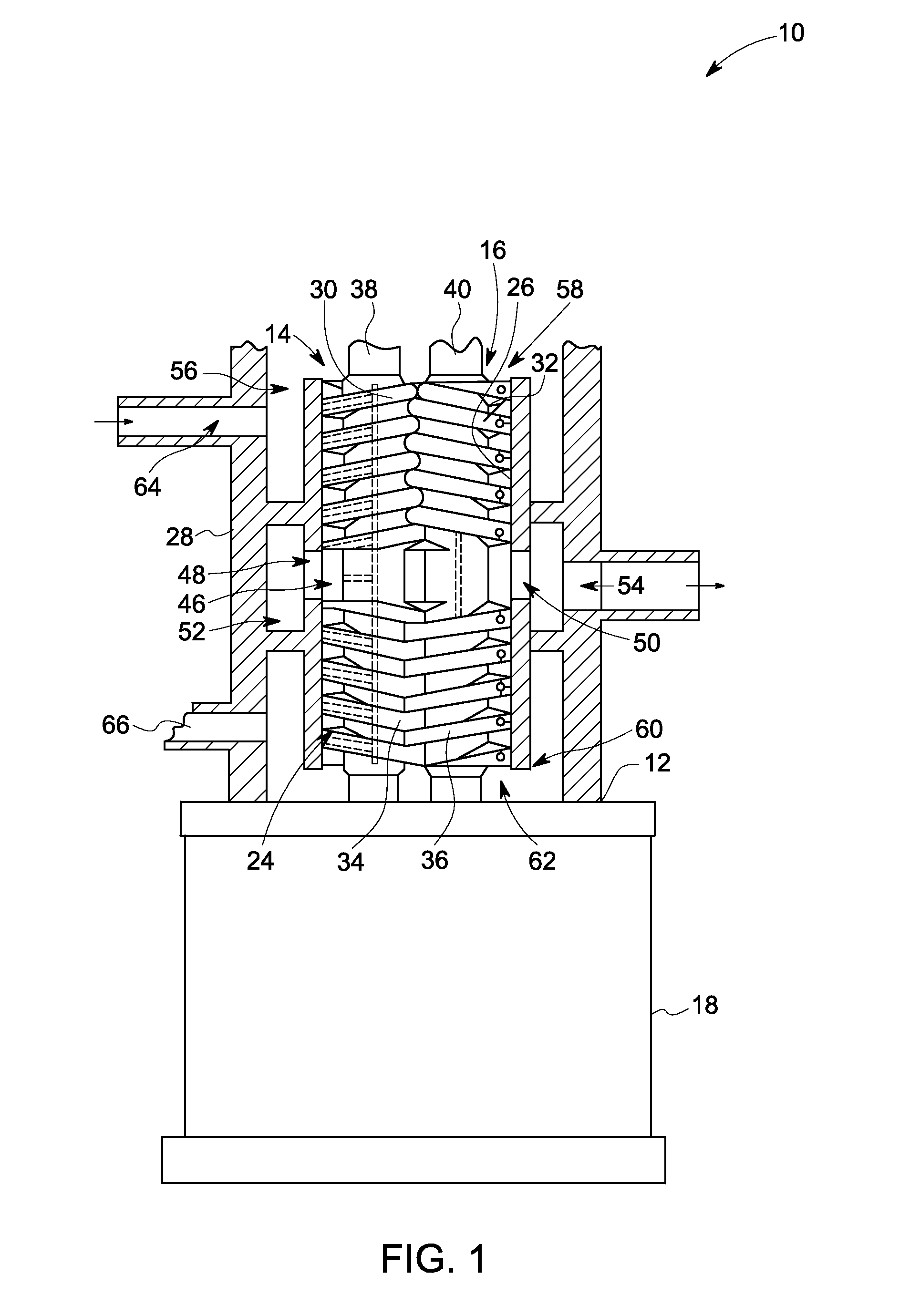
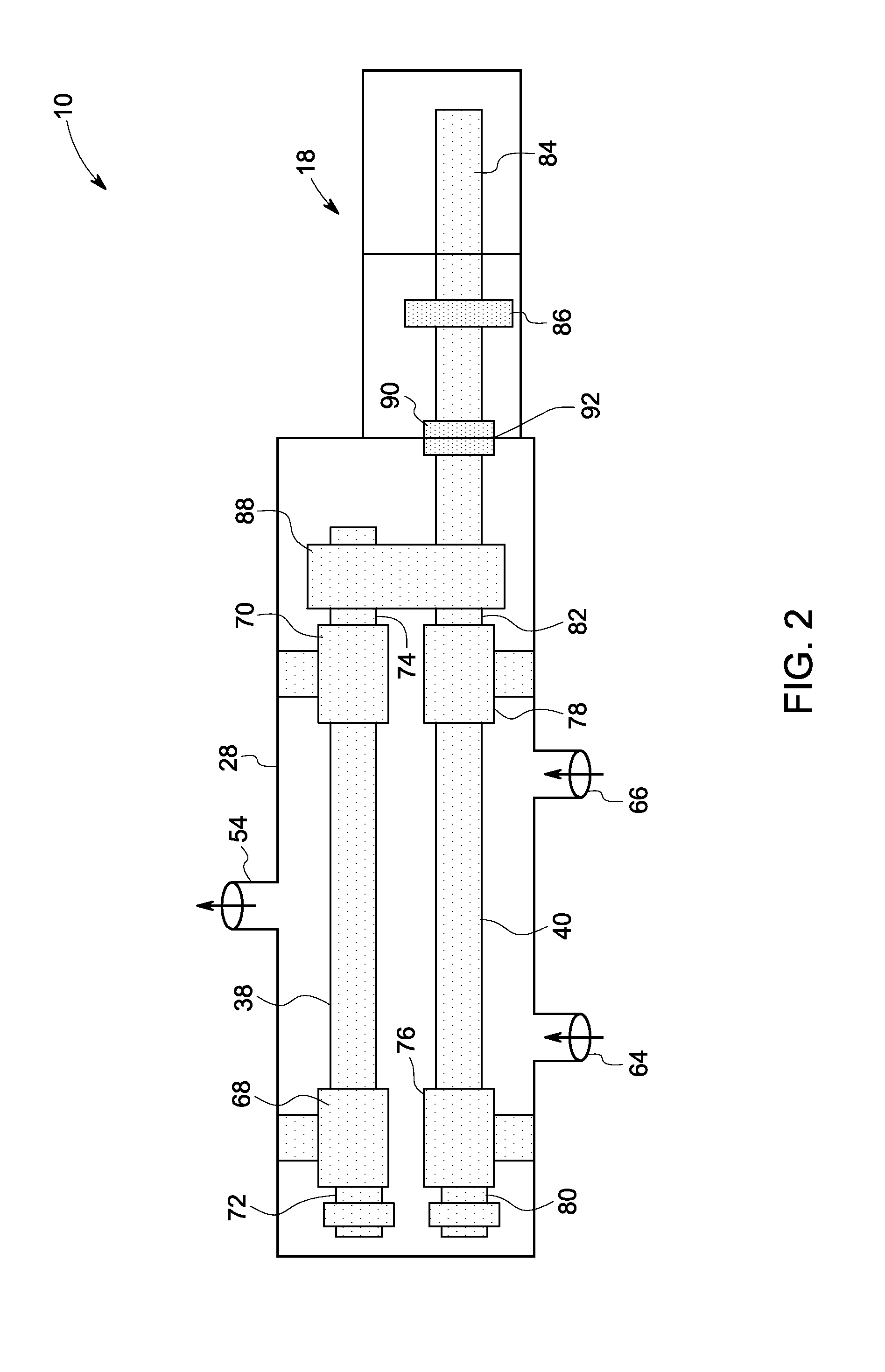
[0017]As discussed in detail below, exemplary embodiments disclosed herein provide a twin screw pump configured to transfer a process fluid, having a pair of rotors placed inside a casing. A pair of bearings is coupled respectively to both ends of the shaft of each rotor. The pair of bearings is not separated from the process fluids by seals and is lubricated by the process fluid medium. In one exemplary embodiment, a system configured to transfer a liquid medium is provided. The system includes a pump coupled to a motor and configured to be driven by the motor. A single seal is coupled to a shaft of one of the rotors of the pump and is located at a predetermined point between the motor and pump. The seal is configured between the motor and the pump to allow the motor to utilize a clean fluid for its purposes without contamination from the process fluids. In another exemplary embodiment, the shaft bearings of the twin screw pump includes ceramic or ceramic matrix composite bearings....


PUM


Abstract

A twin screw pump includes a pair of rotors disposed inside a casing having an inlet and an outlet. Each rotor includes a set of threads disposed on a portion of an outer surface of a shaft. A first bearing is coupled at a first end of the shaft and a second bearing is coupled at a second end of the shaft. The first and second bearings are not separated by one or more seals. The first and second bearings are configured for being lubricated by the liquid medium of the process fluid when the twin screw pump is in an operational mode.

Description

BACKGROUND[0001]The embodiments disclosed herein relate generally to a screw pump, and more particularly to a rotor assembly of a multi-phase twin screw pump.[0002]Twin screw pumps are rotary, positive displacement pumps that use two screws to transfer high or low viscosity fluids or fluid mixtures along an axis. Typically twin screw pumps have two intermeshing counter-rotating screws. The volumes between the intermeshing screws and a liner or casing transport a specific volume of fluid. As the screws rotate the fluid volumes are transported from an inlet to an outlet of the pump.[0003]Twin screw pumps are increasingly being used to aid in the extraction of oil and gas from on-shore and sub-sea wells. Twin screw pumps lower the back pressure on the reservoir and thereby enable greater total recovery from the reservoir.[0004]Conventional twin screw pumps utilize shaft seals to prevent the flow of process fluids into the bearings, timing gears, motor, environment, or the like. In part...

Claims


Application Information

Patent Timeline
Patent Type & Authority Applications(United States)
IPC IPC(8): F01C1/12
CPCF01C21/02F04C2/16F04C11/001F04C13/001F04C2210/24F04C15/0088F04C15/06F04C29/028F04C2210/14F04C15/0038
Inventor KOTHNUR, VASANTH SRINIVASADREXEL, MICHAEL VINCENTANDERSON, DAVID DELOYDHALLMAN, DARREN LEEQU, RONGHAIDEO, HRISHIKESH VISHVASGHASRIPOOR, FARSHAD
Owner GENERAL ELECTRIC CO
Why Eureka
Try Eureka