Reciprocating compressor

Active Publication Date: 2009-04-23
LG ELECTRONICS INC
View PDF4 Cites 15 Cited by
  • Summary
  • Abstract
  • Description
  • Claims
  • Application Information

AI Technical Summary

Benefits of technology

[0007]Another objective set forth herein is to provide a reciprocating compressor that is configured such that it does not increase, but in fac

Problems solved by technology

However, with conventional reciprocating compressors, there are significant problems associated with assembly.
During assembly, sliding each of the bearing portions past the oil pockets can be di

Method used


Image

  • Reciprocating compressor
  • Reciprocating compressor
  • Reciprocating compressor

Examples


Embodiment Construction

[0016]Reference will now be made in detail to several exemplary embodiments of the present invention. These exemplary embodiments are further illustrated in the accompanying drawings.

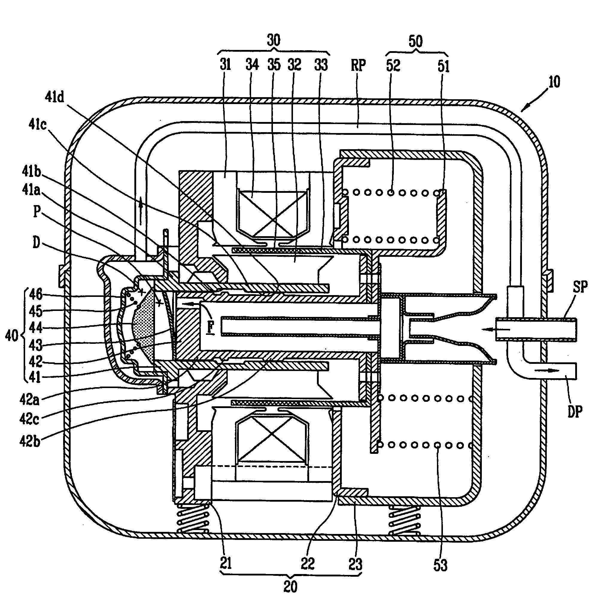
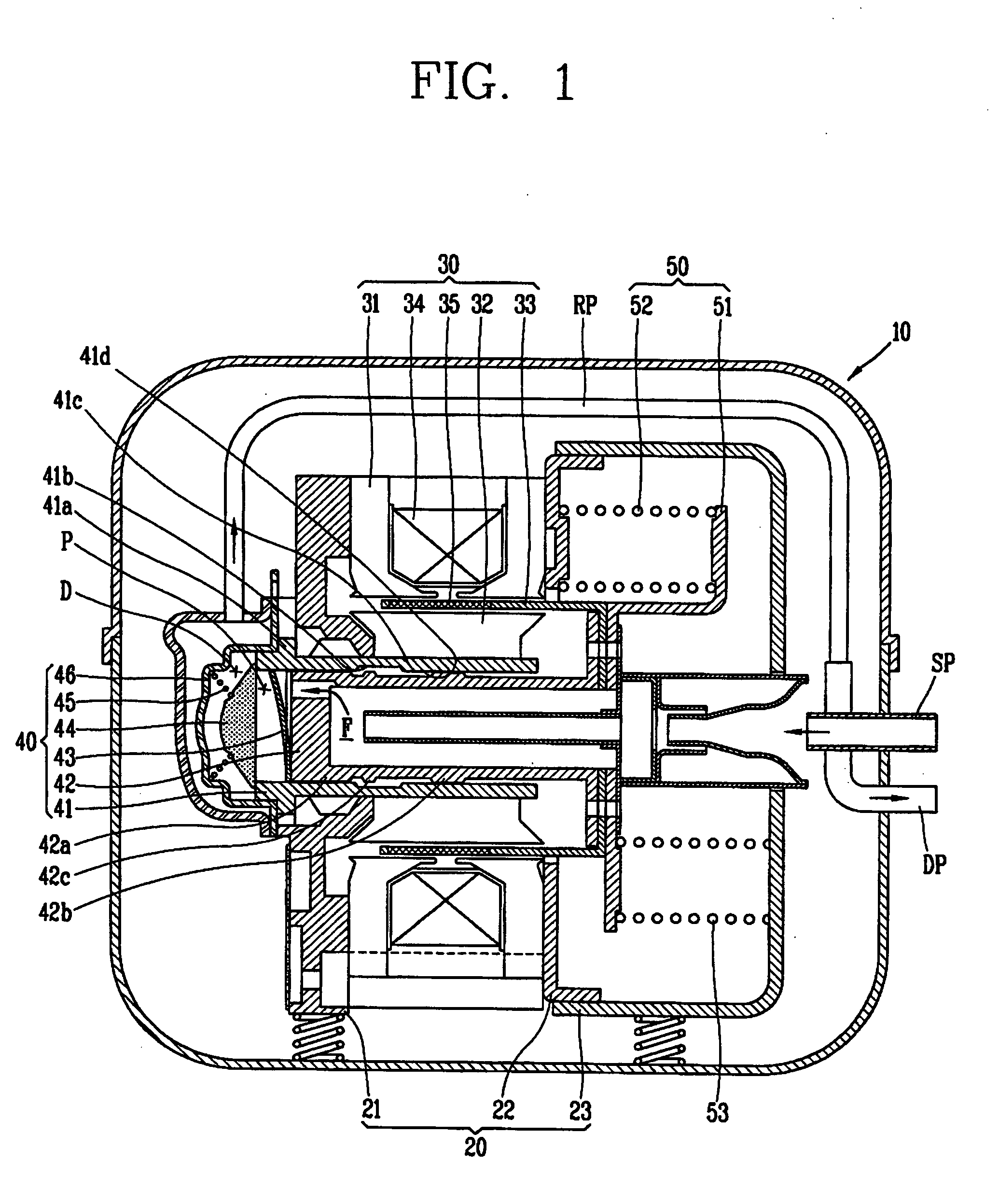
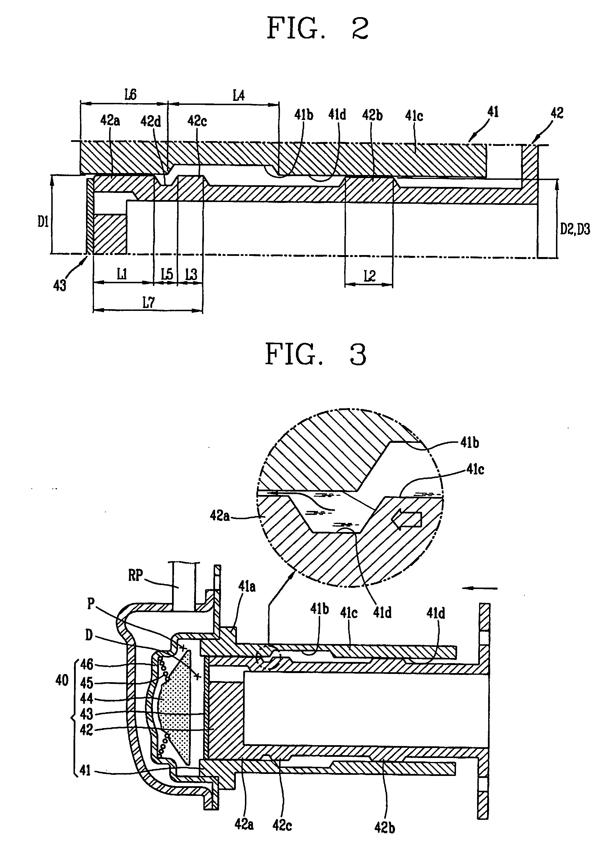
[0017]FIGS. 1-4 present various sectional views of a reciprocating compressor according to a first exemplary embodiment of the present invention. As shown, the reciprocating compressor comprises a casing 10 to which a gas suction pipe SP and a gas discharge pipe DP are connected, and a frame unit 20 elastically supported in the casing 10. The reciprocating compressor also comprises a reciprocating motor 30 supported by the frame unit 20 the reciprocating motor 30 having a mover 33, and a compression unit 40, supported by the frame unit 20, where the compression unit 40 includes a piston 42 coupled to the mover 33 of the reciprocating motor 30. The reciprocating compressor further comprises a plurality of resonant units 50 for inducing a resonant motion in the piston 42 by elastically supporting the move...


PUM


Abstract

A reciprocating compressor comprises: a cylinder having an oil pocket on an inner circumferential surface of a piston insertion hole for inserting a piston with a predetermined width and depth; and a piston having a bearing portion protruding so as to slidably contact an inner circumferential surface of the piston insertion hole, and inserted into the piston insertion hole of the cylinder, wherein the bearing portion is formed to have a length shorter than that of the oil pocket of the cylinder. Accordingly, a frictional loss between the cylinder and the piston is reduced.

Description

[0001]This application claims priority from Korean Application No. 10-2007-0105773, filed on Oct. 19, 2007, which is hereby incorporated by reference in its entirety.BACKGROUND OF THE INVENTION[0002]The present disclosure relates to a reciprocating compressor that includes a cylinder and a piston, and more particularly, to a reciprocating compressor capable of reducing a frictional area between the cylinder and the piston, thereby allowing the piston to more effectively and efficiently reciprocate within the cylinder. The reciprocating compressor is also capable of facilitating the assembly process involving the cylinder and the piston.[0003]Generally, a reciprocating compressor serves to intake, compress, and discharge a refrigerant as a piston linearly reciprocates within a cylinder. The reciprocating compressor may be classified into a connection type reciprocating compressor or a vibration type reciprocating compressor according to the method employed to drive the piston. In the...

Claims


Application Information

Patent Timeline
IPC IPC(8): F01B31/10
CPCF04B35/045F04B39/02F16J10/04F16J1/08F04B39/0276F04B39/00
Inventor KIM, SUNG-GIKIM, DONG-HAN
Owner LG ELECTRONICS INC
Why Eureka
Try Eureka