Low carbon alloy steel tube having ultra high strength and excellent toughness at low temperature and method of manufacturing the same

a low temperature, carbon alloy steel tube technology, applied in the field of low carbon alloy steel tube, can solve the problems of airbag system, inability to meet certain airbag inflator applications, relatively low mechanical properties, etc., and achieve rapid induction austenizing/high speed quench/no temper technique, high tensile strength, and high tensile strength

Inactive Publication Date: 2009-04-23
TENARIS CONNECTIONS
View PDF3 Cites 35 Cited by
  • Summary
  • Abstract
  • Description
  • Claims
  • Application Information

AI Technical Summary

Benefits of technology

[0019]First, the present invention first relates to certain novel low carbon alloy steels suitable for cold forming having more than high tensile strength (UTS 145 ksi minimum) and preferably ultra high tensile strength (UTS 160 ksi minimum and possibly 175 ksi or 220 ksi), and, consequently, a very high burst pressure. Moreover, the steel has excellent toughness at low temperature, with guaranteed ductile behavior at −60° C., i.e., a ductile-to-brittle transition temperature (DBTT) below −60° C., and possibly as low as −100° C.
[0020]Second, the present invention also relates to a process of manufacturing such a steel tube which essentially comprises a novel rapid induction austenizing / high speed quench / no temper technique. In a preferred method, there is an extremely rapid induction austenizing with an ultra fast water quenching step that eliminates any tempering step, so as to create a low carbon alloy steel tube that also is suitable for cold forming having ultra high tensile strength (UTS 145 ksi minimum and up to220 ksi), and, consequently, a very high burst pressure. Moreover, the steel has excellent toughness at low temperature, with guaranteed ductile behavior at −60° C., i.e., a ductile-to-brittle transition temperature (DBTT) that is below −60° C., and possibly even as low as −100° C. The material of the present invention has particular utility in components for containers for automotive restraint system components, an example of which is an automotive airbag inflator. The chemistry used to create each of the steels disclosed herein is novel, hereafter will be identified as Steel A, Steel B, Steel C, Steel D and Steel E, with the compositions for each being summarized in the following Table I:SteelCMnSPCrMoNiVA0.101.230.0020.0080.110.050.340.002B0.101.090.0010.0110.680.410.030.038C0.111.160.0010.0100.640.470.030.053D0.111.070.0020.0080.060.040.030.083E0.100.470.0010.0110.040.020.050.001SteelTiSiCuAlCarbon. eqA0.0230.270.240.0350.38B0.0250.280.220.0350.52C0.0260.250.220.0280.55D0.0010.080.060.0330.33E0.0020.190.070.0270.20

Problems solved by technology

It is believed that most of the examples shown in these documents that are alleged to be ductile after a DW test, would in fact not show ductile behavior at low temperature in a burst test and, therefore, would not qualify for certain airbag inflator applications due to a lack of compliance with governmental regulations (e.g. US DOT).
Various examples are given for a quench and temper material, but mechanical properties obtained are relatively low.
In the past, air bag systems were of the type employing explosive chemicals, but they are expensive, and due to environmental and recycling problems, in recent years, a new type of inflator has been developed using an accumulator made of a steel tube filled with argon gas or the like, and this type is increasingly being used.
These welds are highly critical and as such require considerable labor, and in certain instances testing to assure weld integrity throughout the pressure vessel and airbag deployment.
It has been observed that these welds can crack or fail, thus, risking the integrity of the accumulator, and possibly the operation of the airbag.
This is a destructive-type test in which a canister is subjected to internal pressures significantly higher than those expected during normal operational use, i.e., airbag deployment.

Method used


Image

  • Low carbon alloy steel tube having ultra high strength and excellent toughness at low temperature and method of manufacturing the same
  • Low carbon alloy steel tube having ultra high strength and excellent toughness at low temperature and method of manufacturing the same
  • Low carbon alloy steel tube having ultra high strength and excellent toughness at low temperature and method of manufacturing the same

Examples


Embodiment Construction

[0029]While the present invention is susceptible of embodiment in various forms, it will hereinafter be described a presently preferred embodiment with the understanding that the present disclosure is to be considered an exemplification of the invention and is not intended to limit the invention to the specific embodiment illustrated.

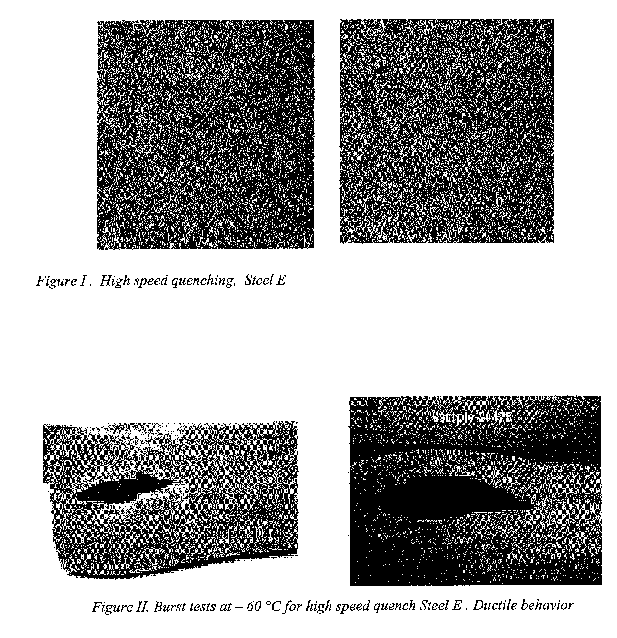
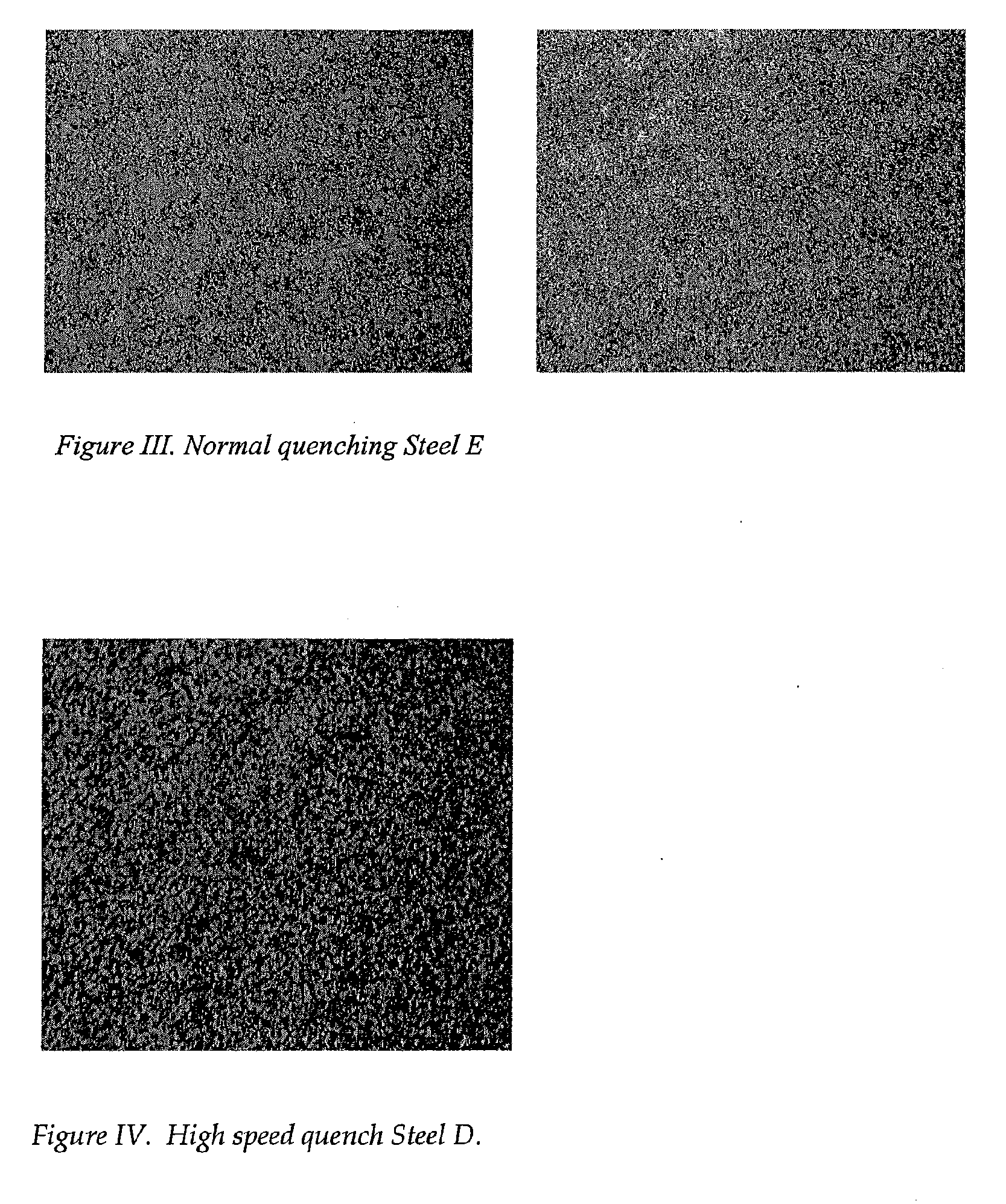
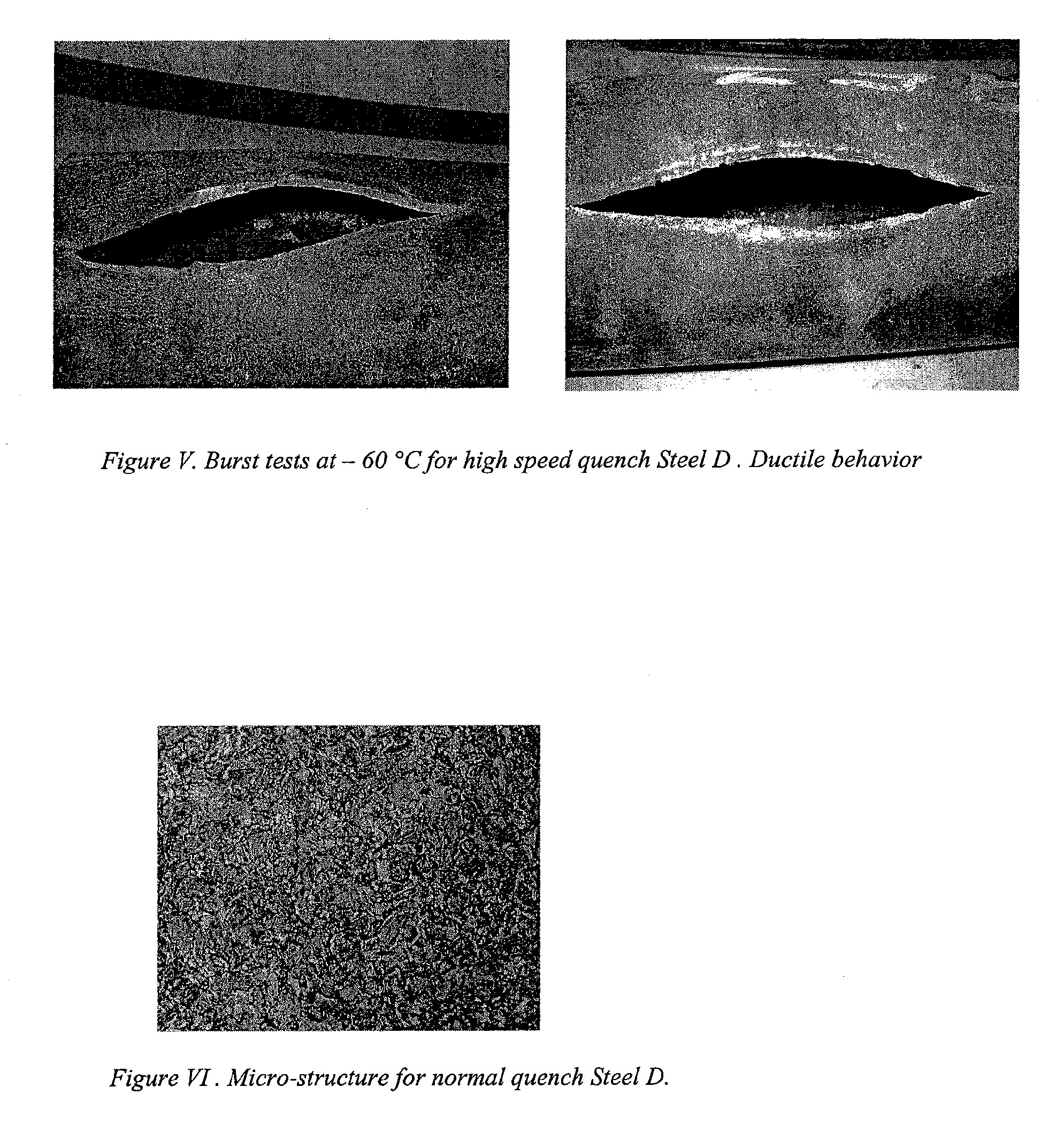
[0030]The present invention relates to steel tubing to be used for stored gas inflator pressure vessels. More particularly, the present invention relates to a low carbon ultra high strength steel grade for seamless pressure vessel applications with guaranteed ductile behavior at −60° C., i.e., a ductile-to-brittle transition temperature below −60° C., and possibly even as low as −100°.

[0031]More particularly, the present invention relates to a chemical composition and a manufacturing process to obtain a seamless steel tubing to be used to manufacture an inflator.

[0032]A schematic illustration of a method of producing the seamless low carbon ultra high s...


PUM

PropertyMeasurementUnit
ductile-to-brittle transition temperatureaaaaaaaaaa
tensile strengthaaaaaaaaaa
yield strengthaaaaaaaaaa

Abstract

A low carbon alloy steel tube and a method of manufacturing the same, especially for a stored gas inflator pressure vessel, in which the steel tube consists essentially of, by weight: about 0.06% to about 0.18% carbon, about 0.3% to about 1.5% manganese, about 0.05% to about 0.5% silicon, up to about 0.015% sulfur, up to about 0.025% phosphorous, and at least one of the following elements: up to about 0.30% vanadium, upto t about 0.10% aluminum, up to about 0.06% niobium, up to about 1% chromium, up to about 0.70 % nickel, up to about 0.70% molybdenum, up to about 0.35% copper, up to about 0.15% residual elements, and the balance iron and incidental impurities. After a high heating rate of about 100° C. per second; rapidly and fully quenching the steel tubing in a water-based quenching solution at a cooling rate of about 100° C. per second. The steel has a tensile strength of at least about 145 ksi and as high as 220 ksi and exhibits ductile behavior at temperatures as low as −100° C.

Description

RELATED APPLICATION[0001]This application is a Continuation-in-part of U.S. Nonprovisional Patent Application No. 10 / 957,605, filed on Oct. 5, 2004.BACKGROUND OF THE INVENTION[0002]1. Field of the Invention[0003]The present invention relates to low carbon alloy steel tubes having ultra high strength and excellent toughness at low temperature and also to a method of manufacturing such a steel tube. The steel tube is particularly suitable for making components for containers for automotive restraint systems, an example of which is an automotive airbag inflator. In addition, alternative steel compositions in the low carbon, low alloy category and different heat treatment processes were developed and tested in order to decrease the manufacturing cost.[0004]2. Brief Description of the Prior Art[0005]Japanese Publication No. 10-140249 [Application date Nov. 5, 1996] and Japanese Publication No. 10-140283 [Application date Nov. 12, 1996] illustrate in general terms steel chemistry consider...

Claims


Application Information

Patent Timeline
Patent Type & Authority Applications(United States)
IPC IPC(8): C22C38/20
CPCC21D8/00C21D8/10C21D9/08C21D9/50C22C38/02C22C38/44C22C38/06C22C38/20C22C38/22C22C38/24C22C38/28C22C38/04
Inventor LOPEZ, EDGARDO OSCARALTSCHULER, EDUARDO
Owner TENARIS CONNECTIONS
Why Eureka
Try Eureka