Manufacturing method of three-dimensional structure and manufacturing device therefor

a manufacturing method and three-dimensional structure technology, applied in the field of three-dimensional structure manufacturing methods, can solve the problems of limited paper material for use in this method, difficult to meet the requirements of three-dimensional structure manufacturing, and limited discussion of the functionality of materials for three-dimensional structures, etc., to achieve the effect of reducing the total formation time of a three-dimensional structure and facilitating cutting

Active Publication Date: 2009-04-23
SEIKO EPSON CORP
View PDF7 Cites 20 Cited by
  • Summary
  • Abstract
  • Description
  • Claims
  • Application Information

AI Technical Summary

Benefits of technology

[0088]With the laser device mentioned above or this mechanical cutter, the porous sheet can be easil

Problems solved by technology

Although metal, ceramic and other materials are used in some of the methods, the realities are that there is little discussion on the functionality of materials for three-dimensional structures.
However, manufacturing three-dimensional structures by using various desired materials is considered to be difficult with the existing three-dimensional modeling methods.
The material for use in this method is limited to paper or some of polymer materials.
In particular, extrusion methods generally supply materials from one nozzle, and therefore has a drawback in that it takes a very long formation time for a three-dimensional structure.
Further, extrusion methods supply materials with relatively high viscosity from the nozzle.
In contrast, regarding inkjet methods, the liquid materials that can be discharged are limited to ones with relatively low viscosity, but their discharge speeds are relatively fast, several KHz, and a large number of nozzles can be used for drawing.
However, there are few inkjet materials such as UV curable resins that have low viscosity during discharge and remain as solids after being cured.
This thin film thickness results in a drawback in that the formation time of a th

Method used


Image

  • Manufacturing method of three-dimensional structure and manufacturing device therefor
  • Manufacturing method of three-dimensional structure and manufacturing device therefor
  • Manufacturing method of three-dimensional structure and manufacturing device therefor

Examples


example 1

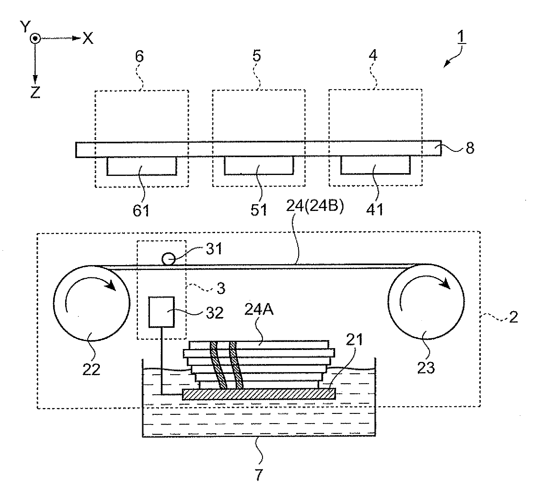
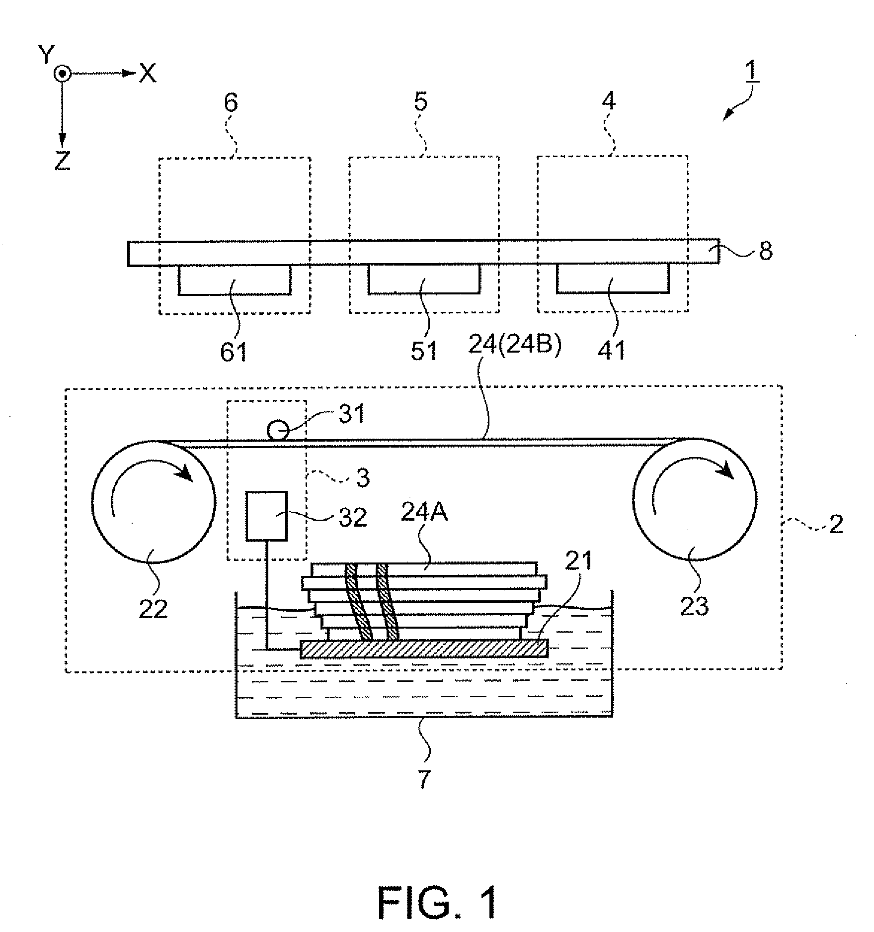
[0095]FIG. 1 is a schematic view of a manufacturing device of a three-dimensional structure of this example.

[0096]A manufacturing device 1 basically includes a sheet supply mechanism 2, a sheet bonding mechanism 3, a sheet processing mechanism 4, a functional liquid imparting mechanism 5, a surface treatment mechanism 6 and a container 7.

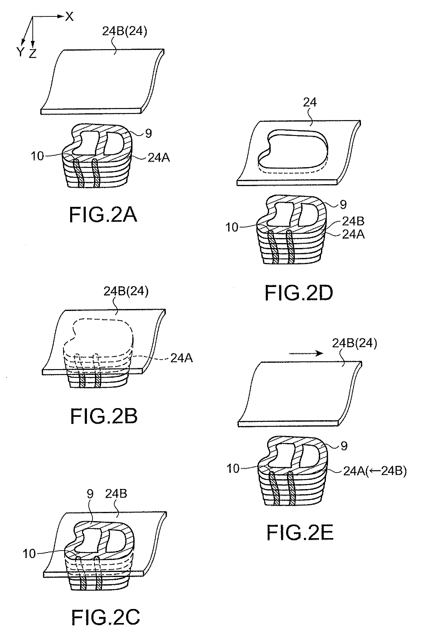
[0097]The sheet supply mechanism 2 is configured so as to place a porous sheet 24B on top of a porous sheet 24A.

[0098]Note that the porous sheet 24A used herein has a predetermined external shape and has at least part thereof containing functional liquids 9 and 10 (FIGS. 2A to 2E).

[0099]Specifically, the sheet supply mechanism 2 of this example includes a support table 21, a supply roll 22 and a collection roll 23.

[0100]One continuous porous mother sheet 24 is wound on the supply roll 22.

[0101]The supply roll 22 supplies the wound porous mother sheet 24 to a side of the collection roll 23.

[0102]The collection roll 23 collects the porous mother sheet...

example 2

[0218]Next, the invention will be described using another example.

[0219]Description will be given on a case where a three-dimensional structure is manufactured with its color tone exactly according to the design.

[0220]The used manufacturing device of a three-dimensional structure is substantially the same as in the example 1.

[0221]However, as the functional liquid discharged from an inkjet head of the inkjet device 51, two kinds of liquids, titania fine particle ink (fine particle size of about 0.2 microns, aqueous solution, titania concentration of 4%) and carbon black ink (fine particle size of about 0.05 microns, aqueous solution, carbon black concentration of 4.5%), were newly added.

[0222]These liquids are ones for coloring the surface of a three-dimensional structure white and black, respectively.

[0223]The porous mother sheet 24 having a thickness of 100 microns, a porosity of 90% and a size of a microstructure (micro-compartment) of about 40 microns was used.

[0224]Regarding a ...


PUM

PropertyMeasurementUnit
Thicknessaaaaaaaaaa
Thicknessaaaaaaaaaa
Thicknessaaaaaaaaaa

Abstract

A manufacturing method of a three-dimensional structure includes (a) placing a second porous sheet on top of a first porous sheet that has a predetermined external shape and at least part of which contains a first functional liquid, (b) bonding at least a range surrounded by a predetermined shape of the second porous sheet onto the first porous sheet, (c) processing the second porous sheet in the predetermined shape, and (d) after step (b), causing a second functional liquid to be contained in at least part of the range of the second porous sheet so that the first functional liquid and the second functional liquid are brought into contact through the first porous sheet and the second porous sheet.

Description

[0001]The entire disclosure of Japanese Patent Application No.: 2007-274748, filed Oct. 23, 2007 is expressly incorporated by the reference herein.BACKGROUND[0002]1. Technical Field[0003]Several aspects of the present invention relate to a manufacturing method of a three-dimensional structure and more particularly to a manufacturing method of a three-dimensional structure in which porous sheets are laminated, and a manufacturing device suitable for practicing the manufacturing method.[0004]2. Related Art[0005]A three-dimensional modeling method, which is also called “rapid prototyping”, is technologies that have been developed so as to evaluate the design and confirm functions by actually manufacturing a designed structure as a three-dimensional object.[0006]In the three-dimensional modeling method, a manufacturing approach called “layered manufacturing” is generally used in which three-dimensional CAD (computer aided design) data in a desired shape is sliced to produce thin plates ...

Claims


Application Information

Patent Timeline
IPC IPC(8): B32B37/02B32B38/14B32B38/04
CPCB29C67/0074Y10T156/17Y10T156/1057Y10T156/1082Y10T156/1751Y10T156/1052Y10T156/1317Y10T156/10Y10T156/12Y10T156/1064Y10T156/108Y10T156/1056B33Y10/00B33Y70/00B33Y30/00B29C64/147B29C64/141
Inventor ISHIDA, MASAYA
Owner SEIKO EPSON CORP
Why Eureka
Try Eureka