In-Wheel Motor Drive Unit

a technology of in-wheel motors and drive units, which is applied in the direction of electric propulsion mounting, electric devices, gearing, etc., can solve the problems of reducing the stability of running, increasing the radial dimension, and serious problems, so as to suppress the torque loss, reduce the contact resistance due to the engagement with the revolution member, and achieve the effect of sufficient torqu

Active Publication Date: 2009-04-23
NTN CORP
View PDF3 Cites 38 Cited by
  • Summary
  • Abstract
  • Description
  • Claims
  • Application Information

AI Technical Summary

Benefits of technology

[0029]Since the outer periphery engagement member is rotatable in the casing, the contact resistance due to the engagement with the revolution member can be reduced. Thus, the in-wheel motor drive unit can suppress a torque loss due to the contact between the revolution member and the outer periphery engagement member.
[003

Problems solved by technology

However, the in-wheel motor drive unit mounted under the spring of the car has a problem that its ride is uncomfortable due to the increase in unsprung weight, so that it has not been practically used yet.
Since the above in-wheel motor drive unit is arranged under a suspension, the problem is that running stability is lowered due to the increase in unsprung weight.
This problem becomes serious as the recent car becomes compact as a whole.
In addition, according to the wheel hub bearing, since the inner ring and outer ring are arranged between the wheel hub and the casing, the problem is that the radial dimension is increased.
Furthermore, since the number of components is large, the assembling pro

Method used


Image

  • In-Wheel Motor Drive Unit
  • In-Wheel Motor Drive Unit
  • In-Wheel Motor Drive Unit

Examples


Embodiment Construction

[0043]An electric car 11 provided with an in-wheel motor drive unit according to one embodiment of the present invention will be described with reference to FIGS. 11 and 12 hereinafter. In addition, FIG. 11 is a plan view showing the electric car 11, and FIG. 12 is a view showing the electric car 11 taken from the back side thereof.

[0044]Referring to FIGS. 11 and 12, the electric car 11 comprises a chassis 12, front wheels 13 as steering wheels, rear wheels 14 as driving wheels, and in-wheel motor drive units 15 transmitting driving force to the right and left rear wheels 14. As shown in FIG. 12, the rear wheel 14 is housed in a wheel housing 12a of the chassis 12, and fixed to the lower part of the chassis 12 through a suspension 12b.

[0045]The suspension 12b supports the rear wheel 14 by suspension arms extending in right and left directions, and suppresses the vibration of the chassis 12 by absorbing the vibration applied from the ground to the rear wheel with a strut including a...


PUM


Abstract

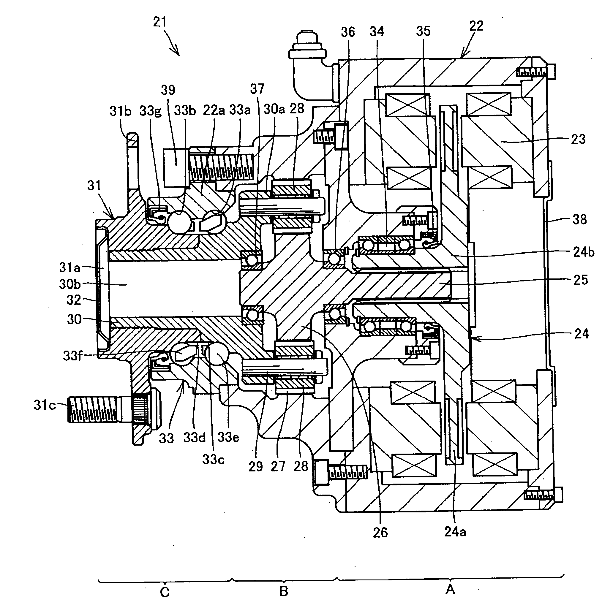
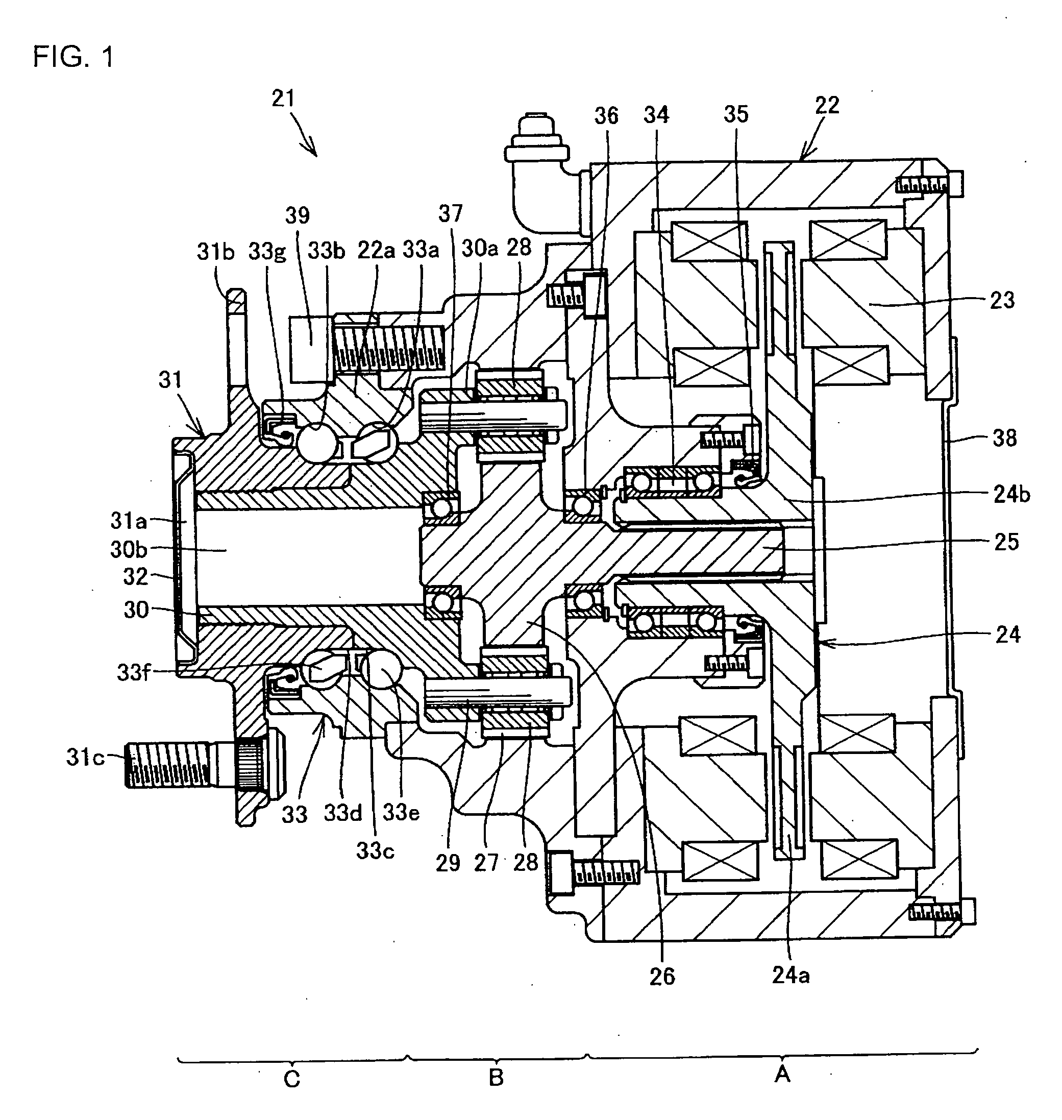
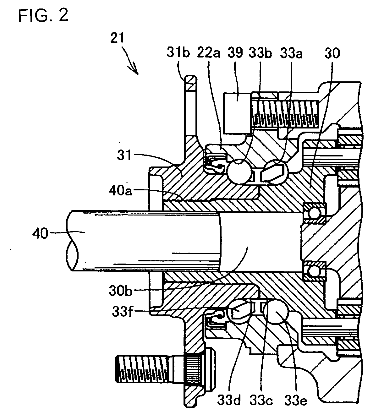
An in-wheel motor drive unit (21) comprises a casing (22), a motor part (A), a deceleration part (B), a wheel hub (31), and a wheel hub bearing (33) rotatably supporting the wheel hub (31) with respect to the casing (22). The wheel hub bearing (33) includes first and second outer track surfaces (33a) and (33b) provided on the inner diameter surface of the casing (22), a first inner track surface (33c) provided on the outer diameter surface of a wheel-side rotation member (30) and opposed to the first outer track surface (33a), a second inner track surface (33d) provided on the outer diameter surface of the wheel hub (31) and opposed to the second outer track surface (33b), and a plurality of rolling elements (33e) arranged between the outer track surfaces (33a) and (33b) and the inner track surfaces (33c) and (33d).

Description

TECHNICAL FIELD[0001]The present invention relates to an in-wheel motor drive unit rotating and driving an individual drive wheel separately.[0002]In addition, the present invention relates to an in-wheel motor drive unit coaxially connecting an output shaft of an electric motor and a hub of a wheel through a decelerator.BACKGROUND ART[0003]A conventional in-wheel motor drive unit is disclosed in Japanese Unexamined Patent Publication No. 2001-32914, for example. The in-wheel motor drive unit disclosed in this document comprises a motor generating driving force, a decelerator decelerating the rotation of the motor and transmitting it to a drive wheel, and a wheel hub rotatably retaining the drive wheel.[0004]The decelerator includes a planet gear mechanism comprising a sun gear provided in an inlet shaft, an internal gear fixed to a casing, and a planet gear arranged between the sun gear and the internal gear, and connected to the output shaft. In addition, the two planet gear mecha...

Claims


Application Information

Patent Timeline
IPC IPC(8): B60K7/00
CPCB60K7/0007B60K17/043B60K17/046B60K2007/0038B60K2007/0092F16C2326/02Y10S903/909F16H1/32H02K7/14H02K7/16H02K21/24Y02T10/641F16H1/28B60L2220/44B60L2220/50F16C19/187Y02T10/64
Inventor SUZUKI, MINORU
Owner NTN CORP
Why Eureka
Try Eureka