In-mould molding touch module and method for manufacturing the same

a touch module and in-mould molding technology, applied in the direction of instruments, casings with display/control units, pulse techniques, etc., can solve the problem of easy thinness, achieve favorable performance, reduce manufacturing time, and simplify manufacturing processes

Active Publication Date: 2009-04-23
TRENDON TOUCH TECHNOLOGY CORPORATION
View PDF3 Cites 14 Cited by
  • Summary
  • Abstract
  • Description
  • Claims
  • Application Information

AI Technical Summary

Benefits of technology

[0008]The touch circuit is an inducing capacitive touch circuit made of indium tin oxide (ITO) or a press touch circuit made of conductive printing ink. The outer surface and the inner surface may define a first touch region coated with an inducing capacitive touch circuit and a second touch region coated with a press touch circuit. Therefore, the in-mould molding touch module has a thin thickness, and eliminates a ladderlike thickness and a gap arranged between the joint surfaces. Consequently, the in-mould molding touch module can avoid congregating the dust, and is prone to be thin.
[0014]The plastic film may be made of a soft rubber film having a heat-resistance capability higher than the temperature in the injecting mold and the vacuum sputtering process, and the ITO layer has heat-resistance capability higher than the temperature in the injecting mold. Thus, the method can be performed favorably, and can simplify the manufacturing processes and decrease the manufacturing time. Furthermore, the inducing capacitive touch circuit can be replaced by a press touch circuit, and the press touch circuit is formed by coating a conductive printing ink by a printing mode. In another embodiment, the plastic film has a first touch region and a second touch region. The inducing capacitive touch circuit is formed in the first touch region, and the press touch circuit is formed in the second touch region. Accordingly, the method is prone to manufacture a touch panel of an electric device having a single sense touch region, and the method has a characteristic of thin design.

Problems solved by technology

Consequently, the in-mould molding touch module can avoid congregating the dust, and is prone to be thin.

Method used


Image

  • In-mould molding touch module and method for manufacturing the same
  • In-mould molding touch module and method for manufacturing the same
  • In-mould molding touch module and method for manufacturing the same

Examples


Embodiment Construction

[0039]Reference will now be made to the drawings to describe a preferred embodiment of the present in-mould molding touch module, in detail.

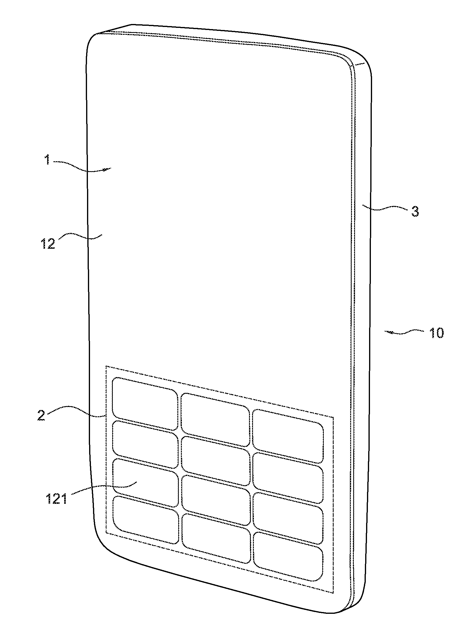
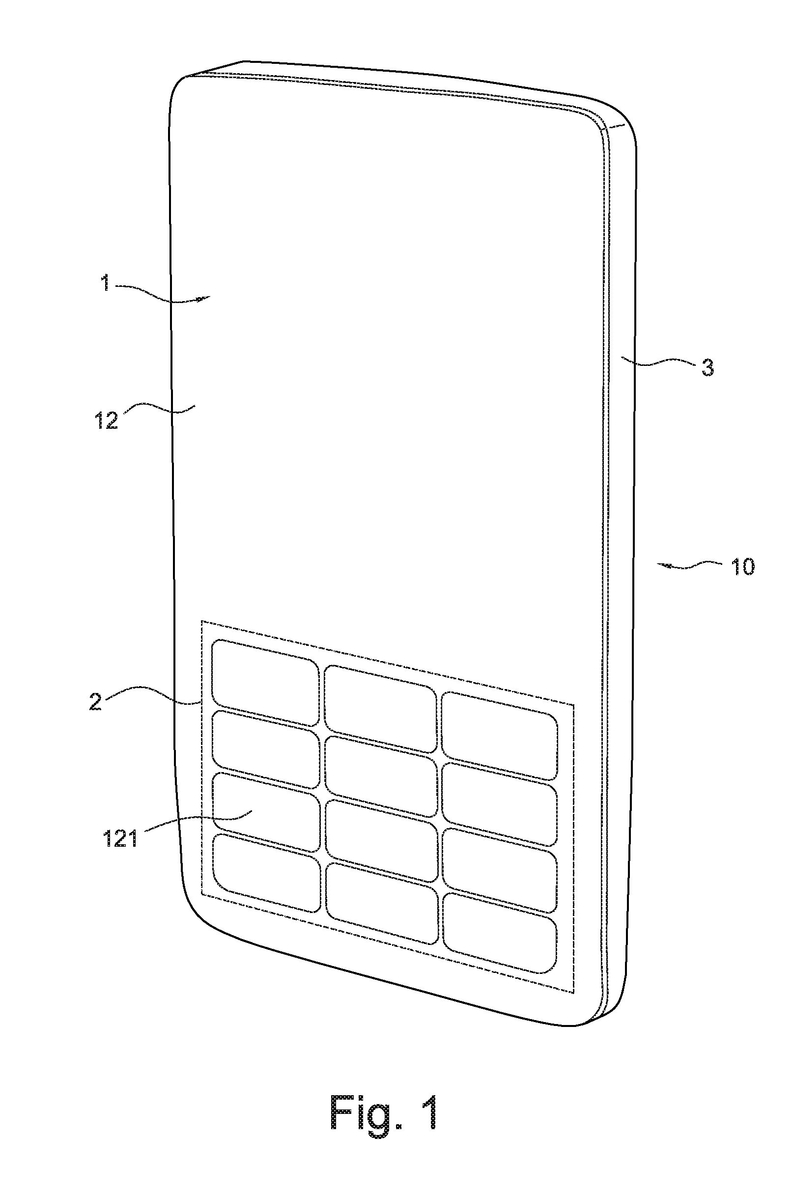
[0040]As shown in FIGS. 1 and 2, an in-mould molding touch module, in accordance with a preferred embodiment of the present invention, is shown. The in-mould molding touch module 10 includes a plastic film 1, a touch circuit 2 and a molding rind 3.

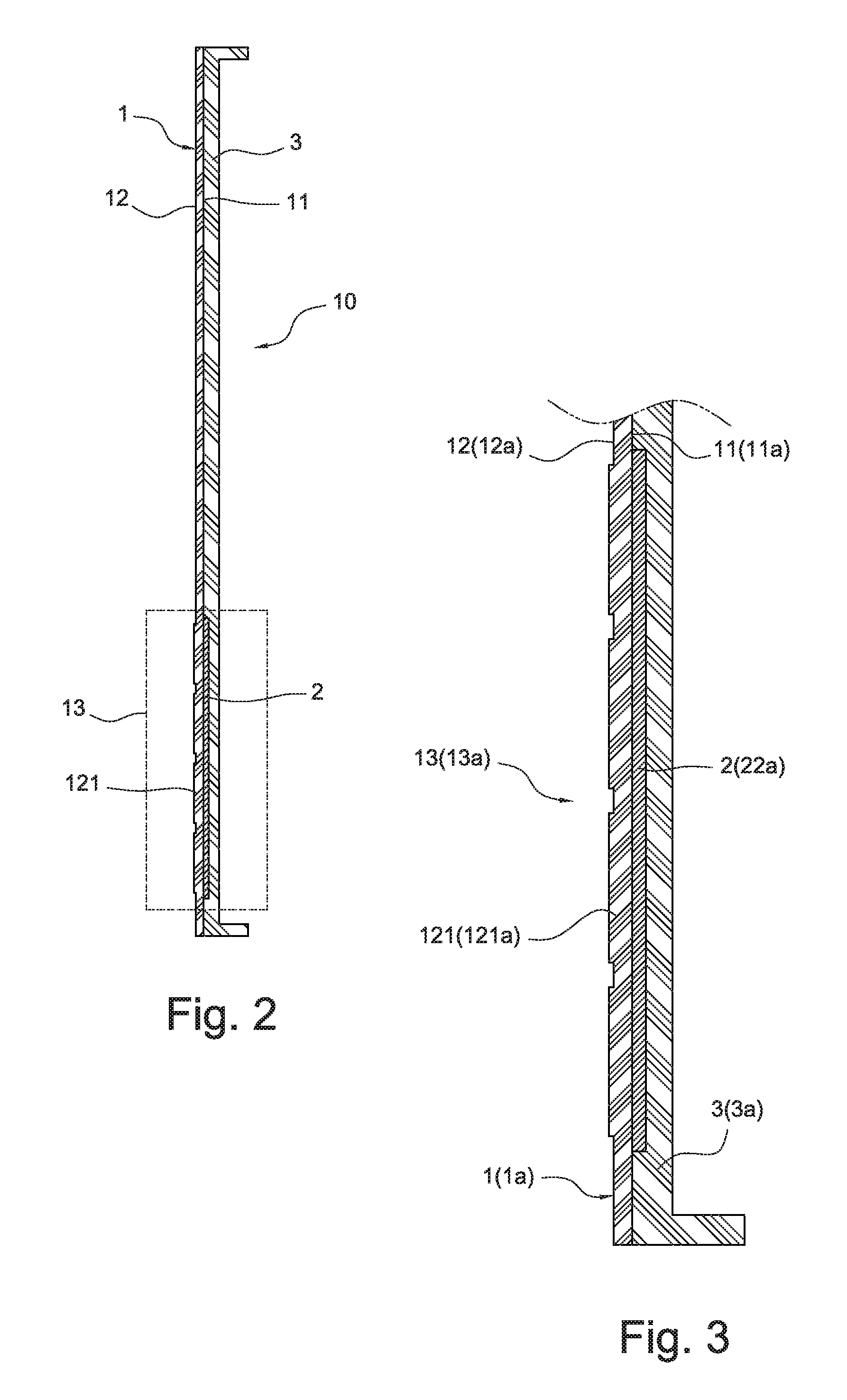
[0041]The plastic film 1 includes an inner surface 11 (as shown in FIG. 3) and an outer surface 12 for handling and touching. A touch region 13 is defined by a region of the inner surface 11 and a corresponding region of the outer surface 12.

[0042]The touch circuit 2 is arranged on the inner surface 11 in the touch sense region 13.

[0043]The molding rind 3 is integrated on the inner surface 11 by an in-mould injecting mode to contain the touch sense circuit 2 for forming a one-piece body.

[0044]In one embodiment, the plastic film 1 can be made of a soft rubber film (as shown in FIGS. 1, 2 and 3). A plura...


PUM

PropertyMeasurementUnit
conductiveaaaaaaaaaa
areaaaaaaaaaaa
transparentaaaaaaaaaa

Abstract

An in-mould molding touch module includes a plastic film, a touch circuit and a molding rind. The plastic film includes an inner surface and an outer surface for handling and touching. At least one region of the inner surface and a corresponding region of the outer surface define a touch area. The touch circuit is arranged on the inner surface in the touch area. The molding rind is integrated on the inner surface by an in-mould injecting mode to contain the touch circuit for forming a one-piece body. In addition, the invention also provides a method for manufacturing an in-mould molding touch module.

Description

1. FIELD OF THE INVENTION[0001]The present invention relates to an in-mould molding touch module and a method for manufacturing the same, and more specifically, to a module technology employing an in-mould injecting technology to contain a touch panel having a sensing circuit.2. DESCRIPTION OF THE RELATED ART[0002]In-mould Touch is a technology deriving from combining an in-mould injecting technology and a manufacturing technology of touch panels.[0003]The in-mould injecting technology in the industry includes an in mold label (IML) technology. A patent WO No. 00 / 39883 discloses an antenna and a method for manufacturing the same, which employ the IML technology. The technology of the patent discloses inserting a plate having a conducting ink antenna circuit printed thereon into a cavity of a mold, and then injects a molding material into the cavity to manufacture the product containing the embedded antenna circuit therein for protecting the antenna circuit, and for preventing the an...

Claims


Application Information

Patent Timeline
Patent Type & Authority Applications(United States)
IPC IPC(8): H03K17/96H01H11/00
CPCH03K2217/960755H01H2201/028H03K17/962H01H2239/006Y10T29/49105H01H2239/074H05K5/0017H01H36/00H01H13/88H04M1/23
Inventor LEE, MIN-YI
Owner TRENDON TOUCH TECHNOLOGY CORPORATION
Why Eureka
Try Eureka