

Rotation sensor and bearing assembly using the same
- Summary
- Abstract
- Description
- Claims
- Application Information
AI Technical Summary
Benefits of technology
Problems solved by technology
Method used
Image

Examples
Embodiment Construction
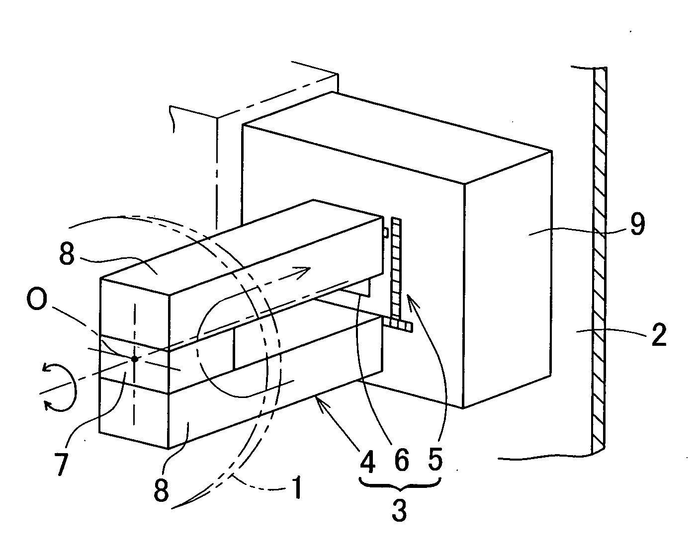
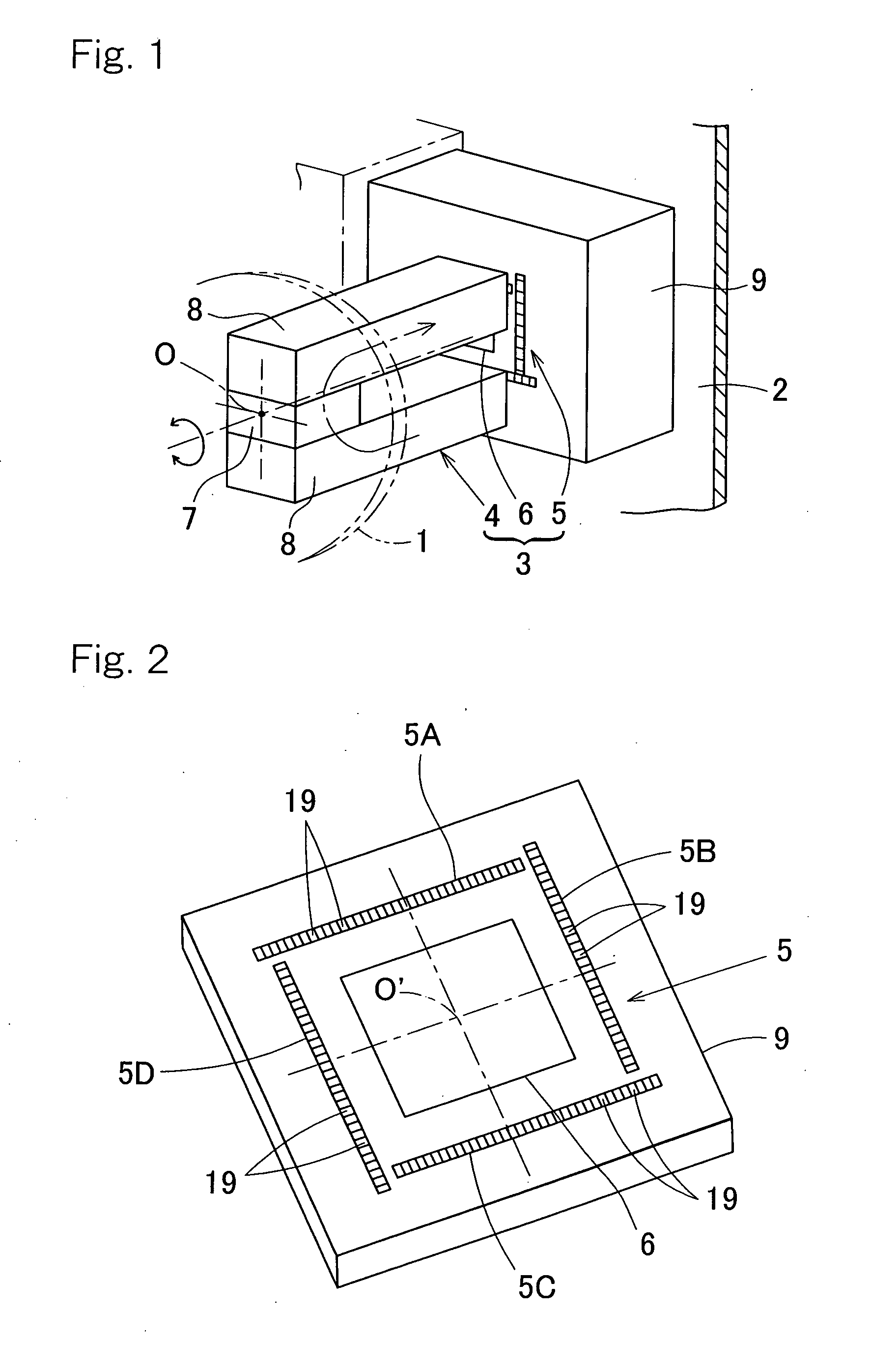
[0022]One embodiment of the present invention will be described in detail. FIG. 1 shows a principle structure of a rotation sensing device according to one embodiment of the present invention. A rotation sensing device 3 includes a rotatable member 1 and a stationary member 2 representing a member on a rotatable side and a member on a stationary side, respectively, which are rotatable relative to each other. This rotation sensing device 3 further includes a magnetic sensor array 5 arranged on the stationary member 2; a magnet 4 which is arranged on the rotatable member 1 and is capable of rotating integrally with the rotatable member 1 with confronting the magnetic sensor array 5, and angle detector unit 6 for detecting an angle of rotation of the magnet 4 from the outputs of the magnetic sensor array. The magnetic sensor array 5 includes a plurality of magnetic sensor elements 19 arranged in line, and is slightly spaced from the magnet 4.
[0023]The magnet 4 is of a type capable of g...
PUM
 Abstract
Description
Claims
Application Information