
Display device

Active Publication Date: 2009-04-23
DENSO CORP +1
View PDF9 Cites 7 Cited by
  • Summary
  • Abstract
  • Description
  • Claims
  • Application Information

AI Technical Summary

Benefits of technology

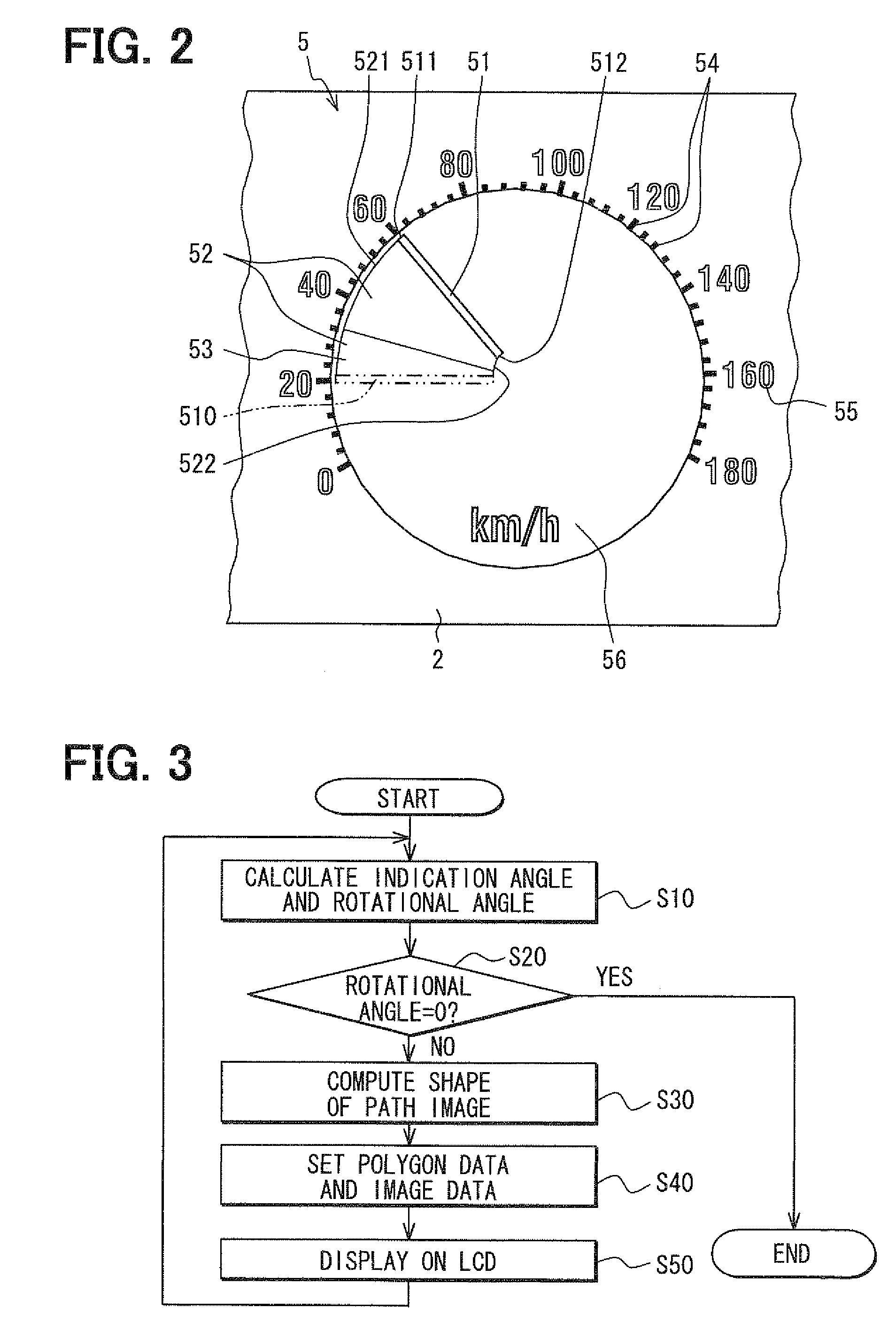
[0008]Accordingly, since the path image of the first frame is displayed over an area between the second location where the pointer image of the second frame was displayed and the first location where the pointer image of the first frame is displayed, that is, the path image of the first frame is displayed continuously from the second location to the first location, it is less likely that the motion of the pointer image will be visible discontinuous between the second frame and the first frame. That is, the pointer image can be shown to move smoothly. Accordingly, an appearance of the motion of the pointer image improves.
[0009]According to a second aspect of the present invention, the control unit is configured to prohibit the path image of the first frame from being displayed when a distance between the pointer image of the second frame and the pointer image of the first frame is equal to or less than a predetermined distance. In a case where the distance between the pointer image of the second frame and the pointer image of the first frame is equal to or less than the predetermined distance, that is, a speed of the motion of the pointer image from the second frame to the first frame is equal to or less than a predetermined speed, the pointer image will be hardly shown discontinuously. In such a case, therefore, even when the path image is not displayed, it is possible to recognize the pointer image moving smoothly.
[0011]For example, the gradation portion is displayed at a portion adjacent to the second location, and is displayed in a gradation manner such that a color tone gradually varies from a color tone of the pointer image to a color tone of a background of the pointer image, toward the second location. In such a case, the persistence of vision of the motion of the pointer image can be blurred adjacent to the second location. Therefore, the recognizability of the motion of the pointer image can be improved by the path image with the gradation portion.
[0012]As another example, the gradation portion can be provided at a first portion of the path image adjacent to the first location and a second portion of the path image adjacent to the second location. In the first portion, the color tone gradually varies from the color tone of the background of the pointer image to the color tone of the pointer image, toward the first location. In the second portion, the color tone gradually varies from the color tone of the background to a color tone of the pointer image of the second frame, toward the second location. In such a case, a continuous appearance between the path image and the pointer image at the first location is improved while highlighting the second location and the first location.
[0013]As further another example, in a case where the pointer image is displayed to move in a rotational manner, the path image is displayed in the fan shape. In such a case, the gradation portion can be provided adjacent to a circumference of the fan shape such that the color tone gradually varies from the color tone of the pointer image to the color tone of the background, as a function of distance from a center of the fan shape. In the case where the pointer image is displayed to move in the rotational manner, a distance of motion of an outer end is greater than a distance of motion of an inner end, when the pointer image moves from the second location to the first location. That is, the outer end of the pointer image moves more than the inner end of the pointer image. In such a case, the persistence of vision of the pointer image is more blurred to the outer end. Accordingly, the recognizability of the motion of the pointer image can be improved.

Problems solved by technology

That is, it is difficult to display the pointer image to move smoothly.

Method used


Image

  • Display device
  • Display device
  • Display device

Examples


Embodiment Construction

[0021]Hereinafter, an exemplary embodiment of the present invention will be described with reference to the accompanying drawings.

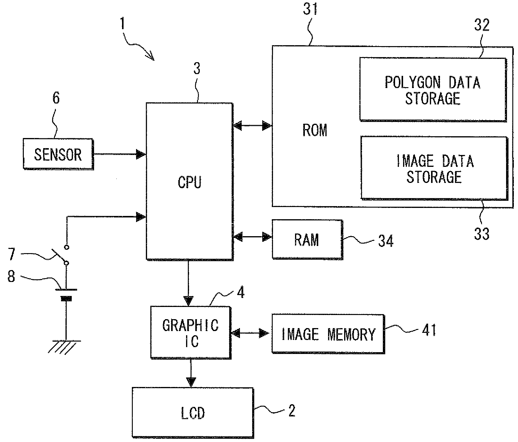
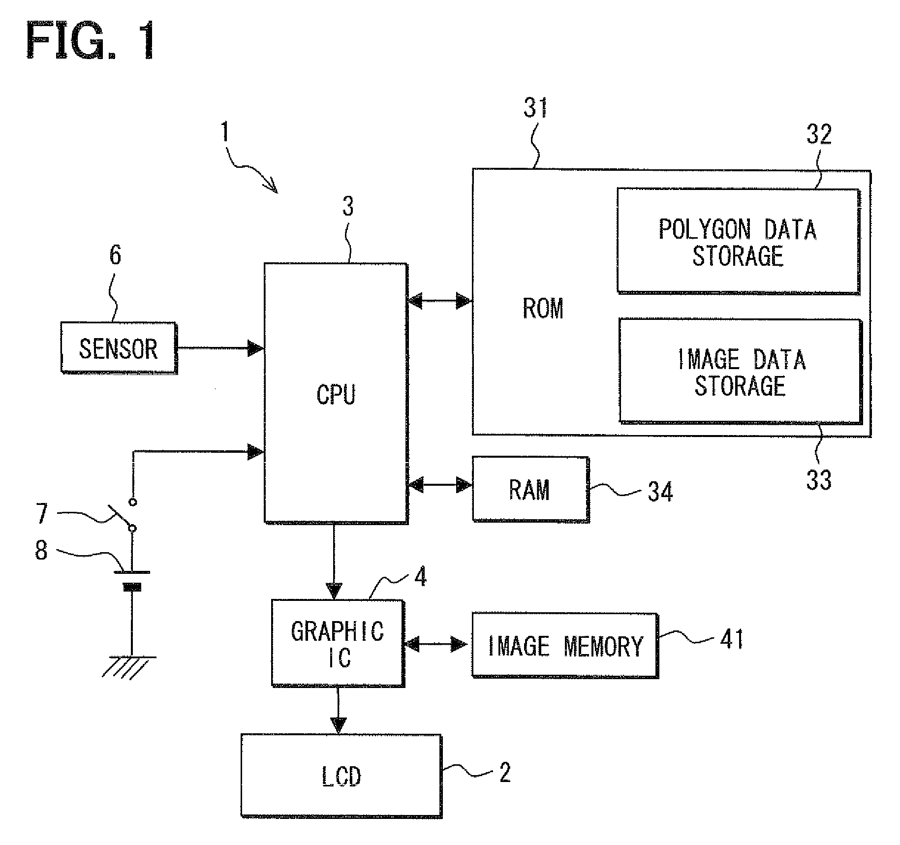
[0022]Referring to FIG. 1, a display device 1 of the present embodiment is, for example, used as a vehicular display device. The display device 1 is provided with a display panel 2, a CPU (central processing unit) 3 and a graphic IC (integral circuit ) 4 as a control unit, a ROM (read only memory) 31, a RAM (random access memory) 34 and an image memory 41.

[0023]The display panel 2 is, for example, a liquid crystal panel 2. A plurality of pixels is formed in the liquid crystal panel 2 in a matrix shape. The liquid crystal panel 2 is, for example, a liquid crystal panel of an active matrix system driven by a thin film transistor (TFT) (not shown). Each of the pixels houses a red pixel, a green pixel and a blue pixel therein, and a voltage is applied to a gate of TFT to control a voltage applied to each of the red pixel, the green pixel and the blue pixel in...


PUM


Abstract

A display device includes a display panel and a control unit. The control unit is configured to control a display condition of the display panel by successively switching a plurality of frames, thereby to display a pointer image indicating a pointer and a path image indicating a path of motion of the pointer image. The path image of a first frame, which is any one of the plurality of frames, is provided continuously from a second location where the pointer image of a second frame, which is another one of the multiple frames and immediately before the first frame, is displayed to a first location where the pointer image of the first frame is displayed.

Description

CROSS REFERENCE TO RELATED APPLICATION[0001]This application is based on Japanese Patent Application No. 2007-273109 filed on Oct. 19, 2007, the disclosure of which is incorporated herein by reference.FIELD OF THE INVENTION[0002]The present invention relates to a display device for displaying a pointer image indicating a pointer.BACKGROUND OF THE INVENTION[0003]For example, JP-A-2003-137007 describes a display device having a display panel such as a liquid crystal panel in which a plurality of pixels is formed in the form of matrix. In the described display device, a pointer image indicating a pointer and a path image indicating rotational motion of the pointer image are displayed on the display panel.[0004]In such a display device, an area where the pointer image moves in a rotational manner is separated into multiple fan-shaped sections with respect to a direction of rotation of the pointer image, and one of the multiple fan-shaped sections is displayed as the path image. For exam...

Claims


Application Information

Patent Timeline
IPC IPC(8): G09G5/08
CPCB60K35/00B60K2350/203B60K37/02B60K2350/1072B60K35/60B60K35/213B60K2360/33
Inventor OKUMURA, TOMOHIRONISHIKAWA, RYOICHIMURAMATSU, TAKAAKISUGANUMA, SHINJI
Owner DENSO CORP
Learn More