Auto-focus image system

a technology of image system and autofocus, which is applied in the direction of camera focusing arrangement, printers, instruments, etc., can solve the problems of small detection point group, ineffective technique, and inconvenient motion video contrast techniqu

Inactive Publication Date: 2009-04-23
CANDELA MICROSYST S PTE
View PDF28 Cites 63 Cited by
  • Summary
  • Abstract
  • Description
  • Claims
  • Application Information

AI Technical Summary

Problems solved by technology

Although acceptable for still pictures the contrast technique is not suitable for motion video.
Having a small group of detection points is prone to error because noise may be superimposed onto one

Method used


Image

  • Auto-focus image system
  • Auto-focus image system
  • Auto-focus image system

Examples


Embodiment Construction

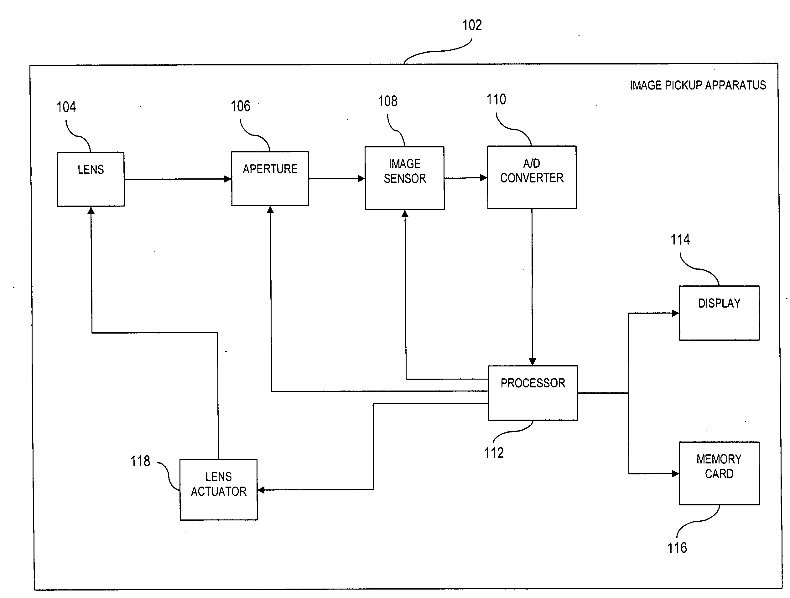
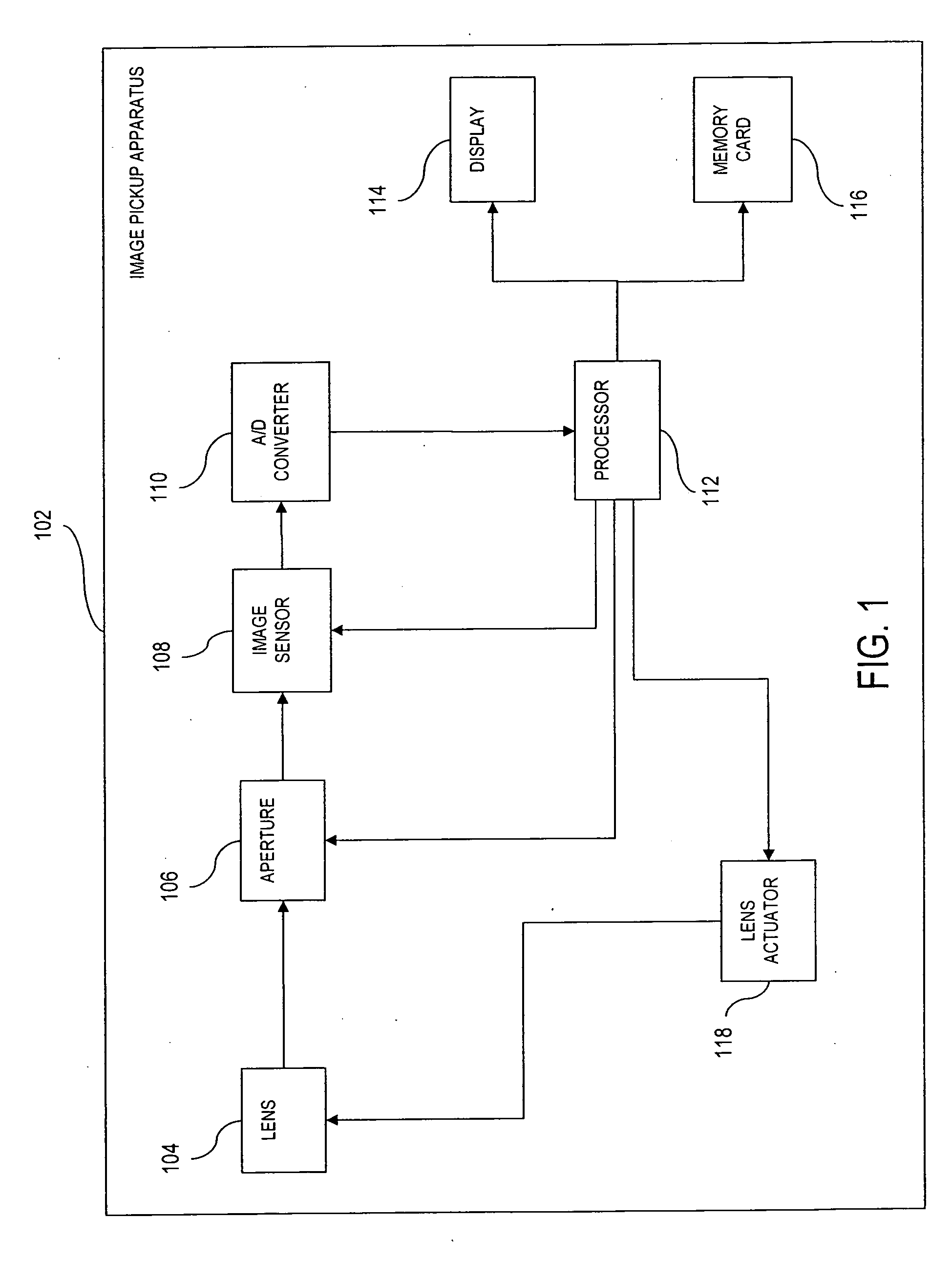
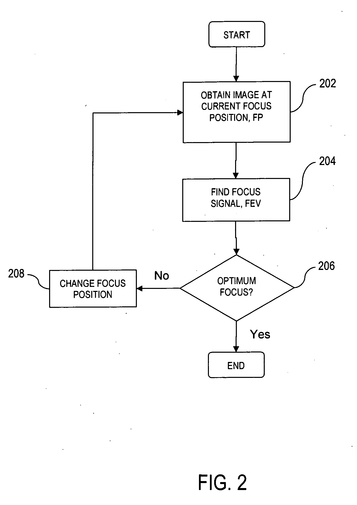
[0038]Disclosed is an auto focus image system that includes an image sensor coupled to a controller. The image sensor captures an image that has at least one edge with a width. The controller generates a focus signal that is a function of the edge width. A lens receives the focus signal and adjust a focus. The edge width can be determined by various techniques including the use of gradients. A histogram of edge widths can be used to determine whether a particular image is focused or unfocused. A histogram with a large population of thin edge widths is indicative of a focused image.

[0039]Referring to the drawings more particularly by reference numbers, FIG. 1 shows an embodiment of an auto-focus image system 102. The system 102 may be part of a digital still camera, but it is to be understood that the system can be embodied in any device that requires controlled focusing of an image. The system 102 may include a lens 104, an aperture 106, an image sensor 108, an A / D converter 110, a ...


PUM


Abstract

An auto focus image system that includes an image sensor coupled to a controller. The image sensor captures an image that has at least one edge with a width. The controller generates a focus signal that is a function of the edge width. A lens receives the focus signal and adjust a focus. The edge width can be determined by various techniques including the use of gradients. A histogram of edge widths can be used to determine whether a particular image is focused or unfocused. A histogram with a large population of thin edge widths is indicative of a focused image.

Description

REFERENCE TO CROSS-RELATED APPLICATIONS[0001]This application claims priority to Application No. 61 / 000,053 filed on Oct. 22, 2007.BACKGROUND OF THE INVENTION[0002]1. Field of the Invention[0003]The subject matter disclosed generally relates to auto-focusing electronically captured images.[0004]2. Background Information[0005]Photographic equipment such as digital cameras and digital camcorders may contain electronic image sensors that capture light for processing into still or video images, respectively. Electronic image sensors typically contain millions of light capturing elements such as photodiodes.[0006]Many image capturing devices such as cameras include an auto-focusing system. The process of auto-focusing includes the steps of capturing an image, processing the image to determine whether it is in focus, and if not, generating a feedback signal that is used to vary the focus of the device lens. There are two primary auto-focusing techniques. The first technique involves contr...

Claims


Application Information

Patent Timeline
IPC IPC(8): H04N5/232G03B17/00
CPCG02B7/36H04N5/23212G03B13/36H04N23/67H04N23/70
Inventor YEO, YUNN-ENTAY, HIOK-NAM
Owner CANDELA MICROSYST S PTE
Why Eureka
Try Eureka