Electrode with Reduced Resistance Grid and Hybrid Energy Storage Device Having Same

a technology of energy storage device and resistance grid, applied in the field of electric motor, can solve the problems of lead-based positive electrode typically failing before the negative electrode, and the positive lead-based electrode of supercapacitor energy storage device typically failing first, so as to reduce the likelihood of failure

Inactive Publication Date: 2009-04-23
AXION POWER INT
View PDF70 Cites 30 Cited by
  • Summary
  • Abstract
  • Description
  • Claims
  • Application Information

AI Technical Summary

Benefits of technology

[0019]It is an advantage of the present invention that there is reduced likelihood of failure of a positive electrode and a hybrid energy storage device containing such a positive electrode.
[0020]In accordance with one aspect of the present invention, an electrode is provided comprising a current collector comprising a grid, the grid comprising a plurality of planar, parallel rows disposed between interleaved rows having raised and lowered segments, and a tab portion extending from a side of the current collector. The rows of raised and lowered segments extend in a horizontal configuration relative to the tab portion, thereby providing substantially uninterrupted conductive ribbons extending from the bottom of the current collector to the tab portion.
[0021]As used herein “substantially”, “generally”, “relatively”, “approximately”, and “about” are relative modifiers intended to indicate permissible variation from the characteristic so modified. It is not intended to be limited to the absolute value or characteristic which it modifies but rather approaching or approximating such a physical or functional cha

Problems solved by technology

Just as with lead-acid batteries, the lead-based positive electrode typically fails before the negative electrode.
Such failures are generally the result of the loss of active lead dioxide paste shedding from the current collector grid as a consequence of spalling and dimensional change deterioration that the active material undergoes during charging and discharging cycles.
It happens that the negative electrodes typically will not wea

Method used


Image

  • Electrode with Reduced Resistance Grid and Hybrid Energy Storage Device Having Same
  • Electrode with Reduced Resistance Grid and Hybrid Energy Storage Device Having Same
  • Electrode with Reduced Resistance Grid and Hybrid Energy Storage Device Having Same

Examples


Embodiment Construction

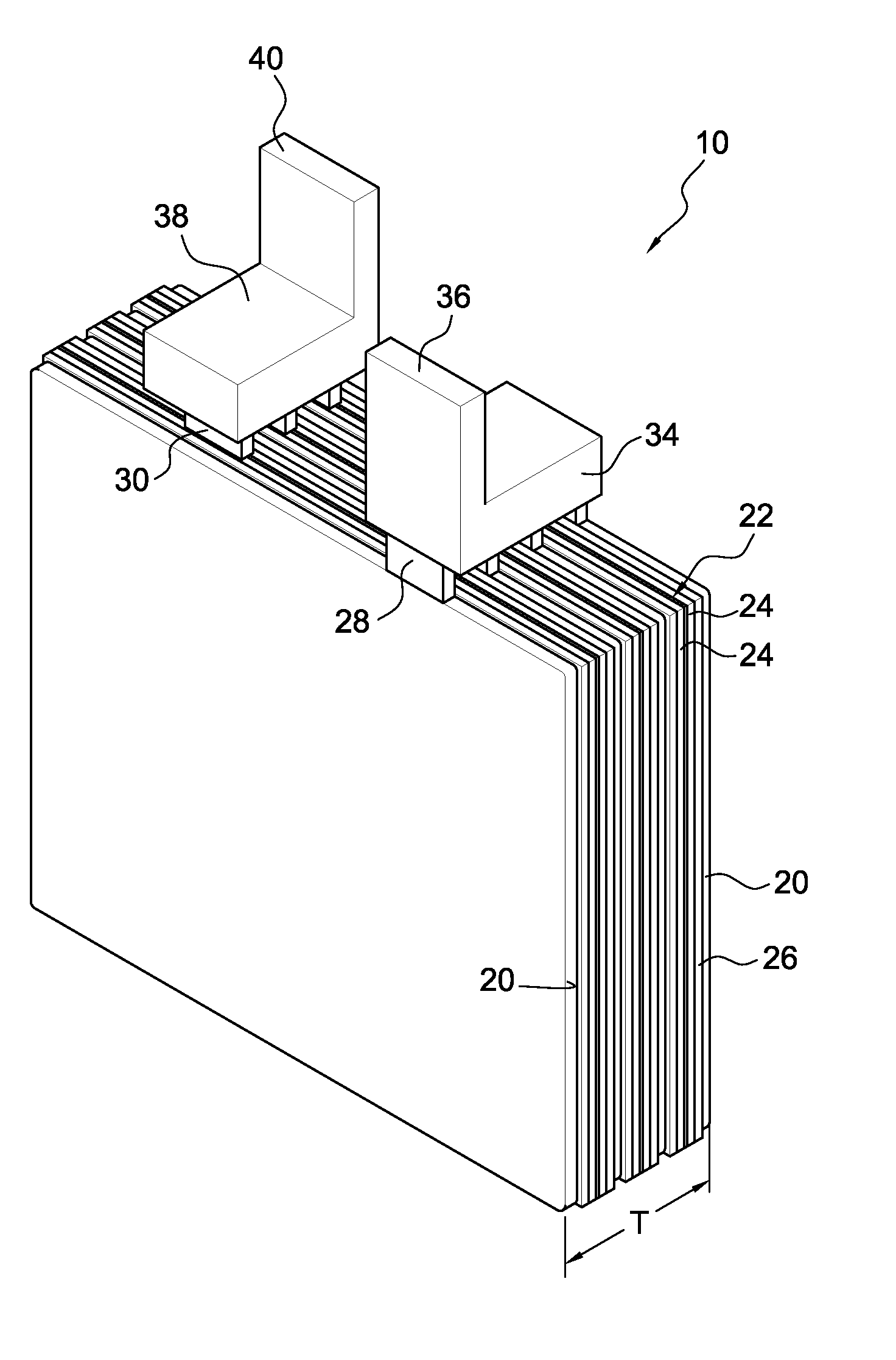
[0068]According to the present invention, a current collector having a reduced resistance grid may be utilized with a positive electrode or a negative electrode. Preferably, the current collector grid is used with a positive electrode. A hybrid energy storage device according to the present invention comprises at least one electrode having a reduced resistance grid according to the present invention.

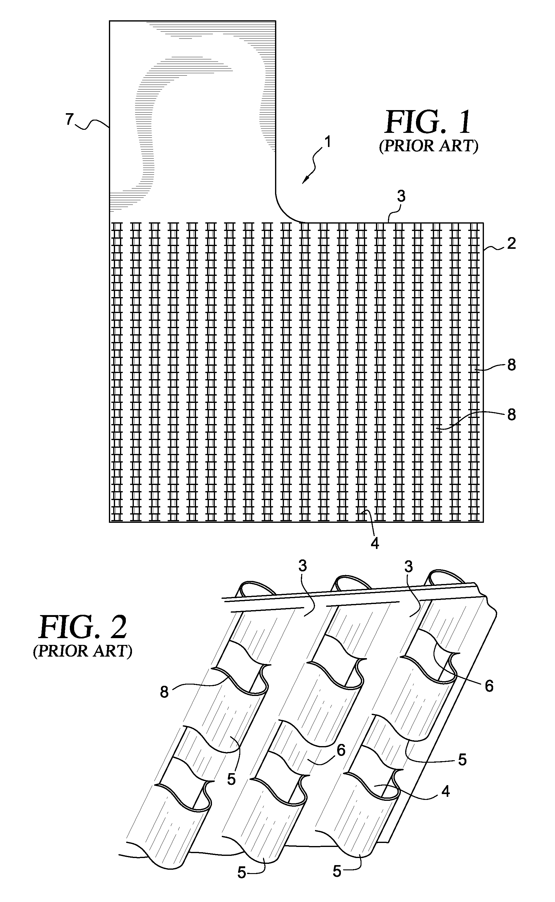
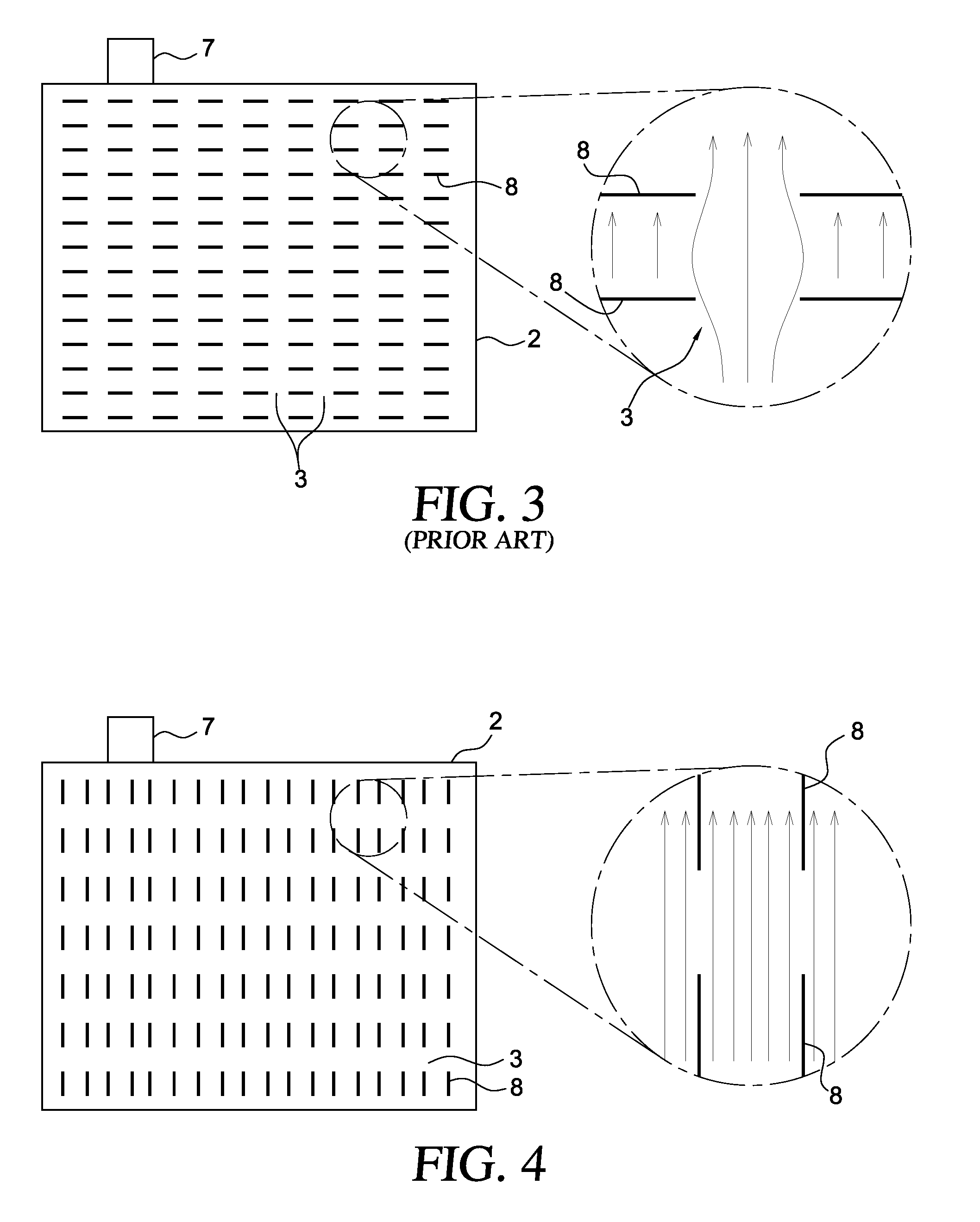
[0069]FIGS. 1-3 illustrate a prior art grid plate 1 of a current collector for an electrode. Generally, the plate 1 is characterized by a grid section 2 disposed below a tab 7 projecting above the upper edge of the plate where the plate incorporates a grid defined by a plurality of continuous, planar, spaced, parallel current channels 3 disposed between interleaved vertical rows 4 of raised and lowered segments 5 and 6.

[0070]Vertical rows 4 are established by punching, machining, or casting a planar sheet of conductive material, particularly metals, or molding the sheet directly which re...


PUM


Abstract

An energy storage device includes at least one positive electrode comprising a current collector comprising lead and having a plurality of raised and lowered portions with respect to a mean plane of the current collector and slots formed between the raised and lowered portions, wherein lead dioxide paste is adhered to and in electrical contact with the surfaces thereof; and a tab portion; and at least one negative electrode comprising a carbon material.

Description

I. RELATED APPLICATIONS[0001]This application is a continuation-in-part application of U.S. Ser. No. 11 / 875,119 filed on Oct. 19, 2007 and claims priority of both U.S. Ser. No. 60 / 853,438 filed on Oct. 23, 2006, the entirety of which is incorporated by reference herein, and U.S. Ser. No. 60 / 891,151 filed on Feb. 22, 2007, the entirety of which is incorporated by reference herein.II. FIELD OF THE INVENTION[0002]This invention relates to an electrode having a reduced resistance grid and to a hybrid energy storage device comprising at least one such electrode.III. BACKGROUND OF THE INVENTION[0003]Hybrid energy storage devices, also known as asymmetric supercapacitors or hybrid battery / supercapacitors, combine battery electrodes and supercapacitor electrodes to produce devices having a unique set of characteristics including cycle life, power density, energy capacity, fast recharge capability, and a wide range of temperature operability. Hybrid lead-carbon energy storage devices employ ...

Claims


Application Information

Patent Timeline
IPC IPC(8): H01G9/155H01M4/02H01M4/58H01M4/583
CPCH01G9/016H01M4/73H01G11/28H01G11/32H01G11/68H01G11/70H01G11/76H01M4/56H01M12/005Y02E60/13H01M2/266H01M4/20H01M4/68H01M4/685H01G9/058Y02E60/10H01G11/74H01G11/22Y02P70/50H01G11/04H01M50/54
Inventor BUIEL, EDWARD R.COLE, JOSEPH E.
Owner AXION POWER INT
Why Eureka
Try Eureka