

Dc-dc converter
a dc-dc converter and converter technology, applied in the direction of transformer/inductance magnetic core, electrical apparatus construction details, printed circuit non-printed electric components association, etc., can solve the problems of low operation, semiconductor devices susceptible to the output voltage fluctuation (ripple) of dc-dc converters, and difficulty in reducing their size, so as to reduce the influence of external noise and facilitate the handling of devices
Active Publication Date: 2009-04-23
HITACHI METALS LTD
View PDF5 Cites 27 Cited by
- Summary
- Abstract
- Description
- Claims
- Application Information
AI Technical Summary
Benefits of technology
[0036]The first main surface of the multi-layer substrate is preferably covered with a resin layer or a metal case connected to the grounded first connecti
Problems solved by technology
However, lower operation voltage makes the semiconductor devices susceptible to the output voltage fluctuation (ripple) of the DC-DC converters.
Among the passive elements, an inductor that should have inductance of at least several μH is large, occupying a large area of the circuit board, and it is not easy to reduce its size.
Further, because the circuit board should have a line pattern connecting the active element and the passive elements, there is a limit to miniaturize the DC-DC converter constituted as a discrete circuit.
The first problem is that a chip inductor CI that should have inductance of several μH cannot be miniaturized like a semiconductor integrated circuit IC.
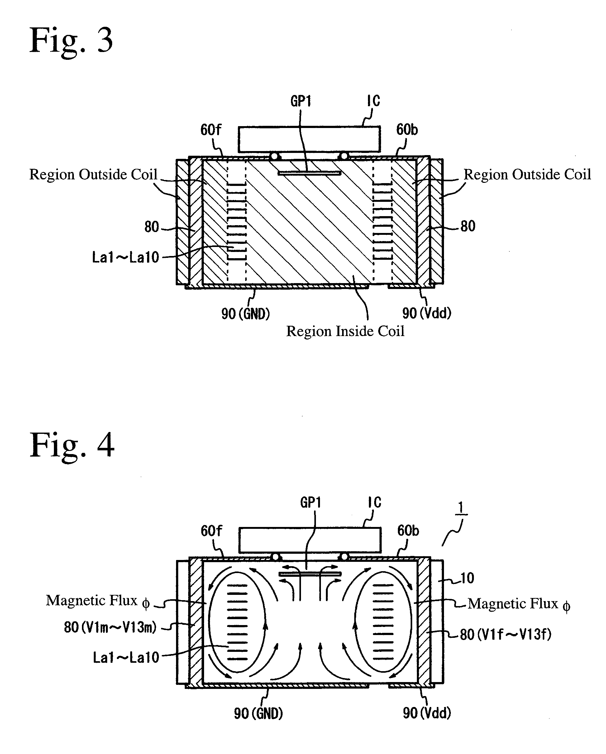
In the DC-DC converter of JP 2005-124271 A, the inductor SI generating a magnetic flux in a transverse direction of the glass-epoxy, multi-layer substrate MS should have a large number of laminated coil turns to have a desired inductance because of a small magnetic path cross section, resulting in difficulty in its miniaturization.
Also, increase in the number of laminated coil turns results in larger DC resistance, which decreases an output voltage Vout.
Thus, the DC-DC converter has low conversion efficiency.
The second problem is a
Method used
View moreImage
Smart ImageViewing Examples

Examples
 PUM
 Abstract
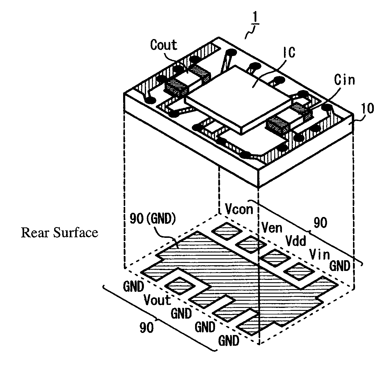
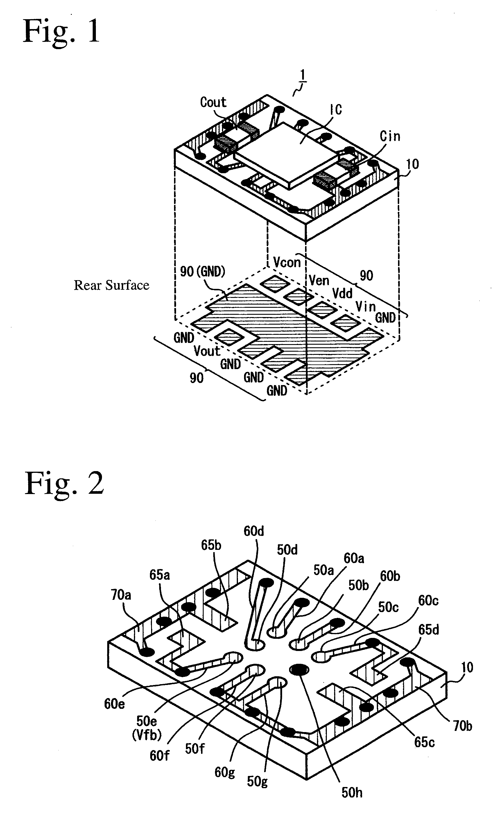
A DC-DC converter comprising a soft-magnetic, multi-layer substrate provided with a laminated coil constituted by connecting pluralities of conductor lines, and a semiconductor integrated circuit device comprising a switching device and a control circuit, which are mounted on the soft-magnetic, multi-layer substrate; the semiconductor integrated circuit device comprising an input terminal, an output terminal, a first control terminal for controlling the ON/OFF of the switching device, a second control terminal for variably controlling output voltage, and pluralities of ground terminals; the soft-magnetic, multi-layer substrate comprising first external terminals formed on a first main surface, first connecting wires formed on the first main surface and/or on nearby layers, second connecting wires formed between the side surface of the multi-layer substrate and a periphery of the laminated coil, and second external terminals formed on a second main surface; and terminals of the semiconductor integrated circuit device being connected to the first external terminals on the multi-layer substrate, at least part of the first external terminals being electrically connected to the second external terminals through the first and second connecting wires, and the input or output terminal being connected to the second external terminals via the laminated coil.
Description
FIELD OF THE INVENTION[0001]The present invention relates to a small DC-DC converter having excellent heat dissipation, with reduced magnetic flux leakage and parasitic inductance.BACKGROUND OF THE INVENTION[0002]Many of various mobile electronics equipments such as cell phones, mobile information terminals PDA, note PCs, mobile audio / video players, digital cameras, video cameras, etc. have DC-DC converters as devices for converting power source voltage to operation voltage. As one example of the DC-DC converter circuits, FIG. 26 shows a step-down DC-DC converter circuit comprising an input capacitor Cin, an output capacitor Cout, an output inductor Lout, and a semiconductor integrated circuit IC comprising a control circuit CC, etc. In the step-down DC-DC converter, switching devices (for instance, field effect transistors) in the semiconductor integrated circuit IC are switched according to a control signal, to lower a DC input voltage Vin to an output voltage Vout [=Ton / (Ton+Toff...
Claims
Login to View More Application Information
Patent Timeline
 IPC IPC(8): H05K1/18
CPCH01F27/292H01F2027/2809H01F2017/0066H01L23/645H01L2924/19103H01L2924/19105H01L2224/16225H02M3/155H01L2924/13091H01F2017/002H01F2017/0086H02M3/00H01F17/0013H01L2924/00H05K2201/10015H05K1/0233H05K1/165H05K2201/086H02M3/003H01L25/00
InventorWATANABE, MITSUHIRO
OwnerHITACHI METALS LTD