(DISC) magnetic torque sensing with segments

Inactive Publication Date: 2009-04-30
ABAS
View PDF18 Cites 19 Cited by
  • Summary
  • Abstract
  • Description
  • Claims
  • Application Information

AI Technical Summary

Benefits of technology

[0017]A torque-sensing element in accordance with the invention may be incorporated in a transducer which also comprises one or more

Problems solved by technology

A problem which can arise with magnetic-based torque sensing in discs, and particularly relatively thin discs, is that the magnetically active disc surface may be warped or may warp such as under the effects of torque or for any other reason, or the surface may not be mounted in an exactly radial plane.
Such warping can result in a modulation of the torque-representing output signal from the sensor arrangement as the disc rotates.
Another problem which may arise is in a procedure for demagnetising or magnetically cleansing the disc or relevant portion of it prior to magnetisation to form a transducer element in the

Method used


Image

  • (DISC) magnetic torque sensing with segments
  • (DISC) magnetic torque sensing with segments
  • (DISC) magnetic torque sensing with segments

Examples


Embodiment Construction

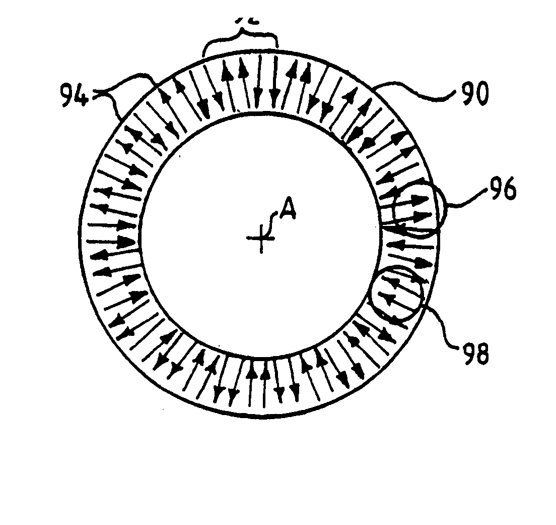
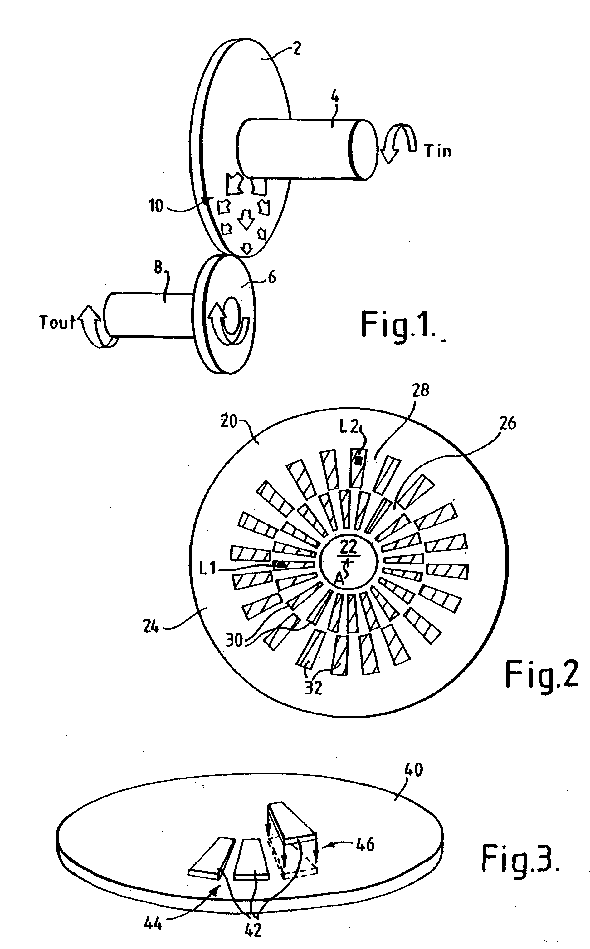
[0040]Referring to FIG. 1, there is shown a torque transmission system in which a gear wheel 2 mounted on a shaft 4 is driven about the axis of the shaft by an input torque Tin. Gear wheel 2 meshes with gear wheel 6 (for simplicity the teeth are not shown) which is mounted to shaft 8 to which a load (not shown) is connected for transmission of output torque Tout thereto. Gear wheel 2 is a disc structure and the radial arrows 10 indicate the direction of torque between the torque entry point from shaft 4 and the torque exit point where the gear wheels engage, The torque stresses in the gear wheel 2 decrease radially towards its periphery as indicated by the size of the arrows so that the stresses are much larger near the centre than at the periphery. It will be understood that the torque transmission could be in the opposite direction.

[0041]The objective is the measurement of the torque in the gear wheel 2. To this end the gear wheel is provided with pulse modulation magnetisation in...


PUM


Abstract

A torque transducer system comprises a disc through which torque is transmitted in a radial direction and which has a magnetised annular region which emanates a torque-dependent magnetic field. A non-contacting magnetic field sensor detects the emanated field. The annular region comprises segments by means of which a pulsed magnetic field is emanated as the disc rotates. The segments may be magnetically unipolar and spatially separated or of alternate polarity. They may be integral with the disc of or material applied to the disc that is magnetised or that segments an underlying magnetisation in the disc. The preferred direction of magnetisation is radial and the effect of the orientation of a sensor with respect to the radial field is discussed. One sensor arrangement comprises a pair of sensors oriented at an angle to one another with reference to the radial field. The teachings of the invention can be applied to the segmentation of an integral transducer region of a torque-transmitting shaft, the region having an annulus of axially-directed remanent magnetization.

Description

FIELD OF THE INVENTION[0001]This invention relates to a magnetic torque-sensing element comprising a disc through which torque is radially transmissible or comprising a member for transmitting torque about a torque axis in the direction of the axis. The invention also relates to a transducer assembly including such a torque-sensing element.[0002]The invention is concerned with a magnetic-based torque sensor for a disc or other structure which is mounted for rotation about an axis and which transmits torque in a generally radial direction. Unless otherwise required by the context, the term “disc” will be used to encompass all such structures. A disc mounted for rotation about an axis includes discs that continually rotate about the axis, discs that rotate to a limited extent and discs which are restrained from significant rotation but in which torque may nonetheless be established.[0003]The invention is also concerned with a magnetic-based torque sensor for a shaft or other member th...

Claims


Application Information

Patent Timeline
IPC IPC(8): G01L3/10G01L3/14
CPCG01L3/1435G01L3/101G01L3/105G01L3/104
Inventor MAY, LUTZ AXEL
Owner ABAS
Why Eureka
Try Eureka