
Liner Drilling and Cementing System Utilizing a Concentric Inner String

a cementing system and inner string technology, applied in the field of oil and gas well drilling, can solve the problems of limiting the length of the liner, not extending back, and not allowing one to employ components that must be retrieved,

Active Publication Date: 2009-04-30
SCHLUMBERGER TECH CORP
View PDF40 Cites 95 Cited by
  • Summary
  • Abstract
  • Description
  • Claims
  • Application Information

AI Technical Summary

Problems solved by technology

However, the liner does not extend back to the wellhead assembly at the surface.
This technique does not allow one to employ components that must be retrieved, which might include downhole steering tools, measuring while drilling instruments and retrievable drill bits.
Being unable to retrieve the bit for replacement thus limits the length that can be drilled and thus the length of the liner.
If unable to retrieve and rerun the bottom hole assembly, the operator would not be able to liner drill with expensive directional steering tools, logging instruments and the like, without planning for removing the entire liner string to retrieve the tools.
If the operator wishes to retrieve the bottom hole assembly before cementing the liner, there are no established methods and equipment for doing so.
Also, if the operator wishes to rerun the bottom hole assembly and continue drilling with the liner, there are no established methods and equipment for doing so.
One difficulty to overcome in order to retrieve and rerun a bottom hole assembly during liner drilling concerns how to keep the liner from buckling if it is disconnected from the drill pipe and left in the well.
But, there is a risk that the liner might buckle due to inadequate strength to support its weight in compression.
However, current technology sets the liner hanger only once, at the conclusion of the drilling and after cementing.

Method used


Image

  • Liner Drilling and Cementing System Utilizing a Concentric Inner String
  • Liner Drilling and Cementing System Utilizing a Concentric Inner String
  • Liner Drilling and Cementing System Utilizing a Concentric Inner String

Examples


Embodiment Construction

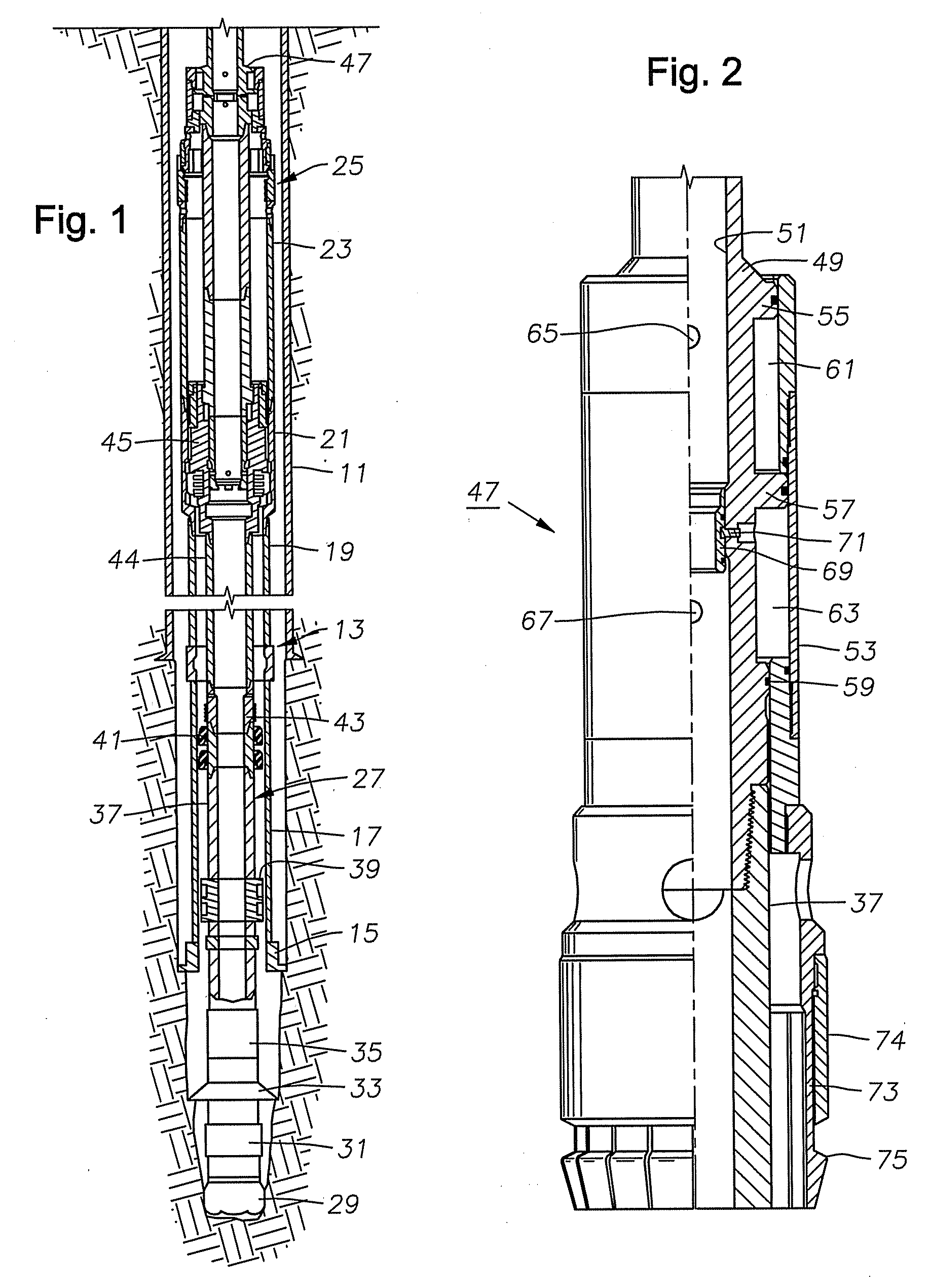
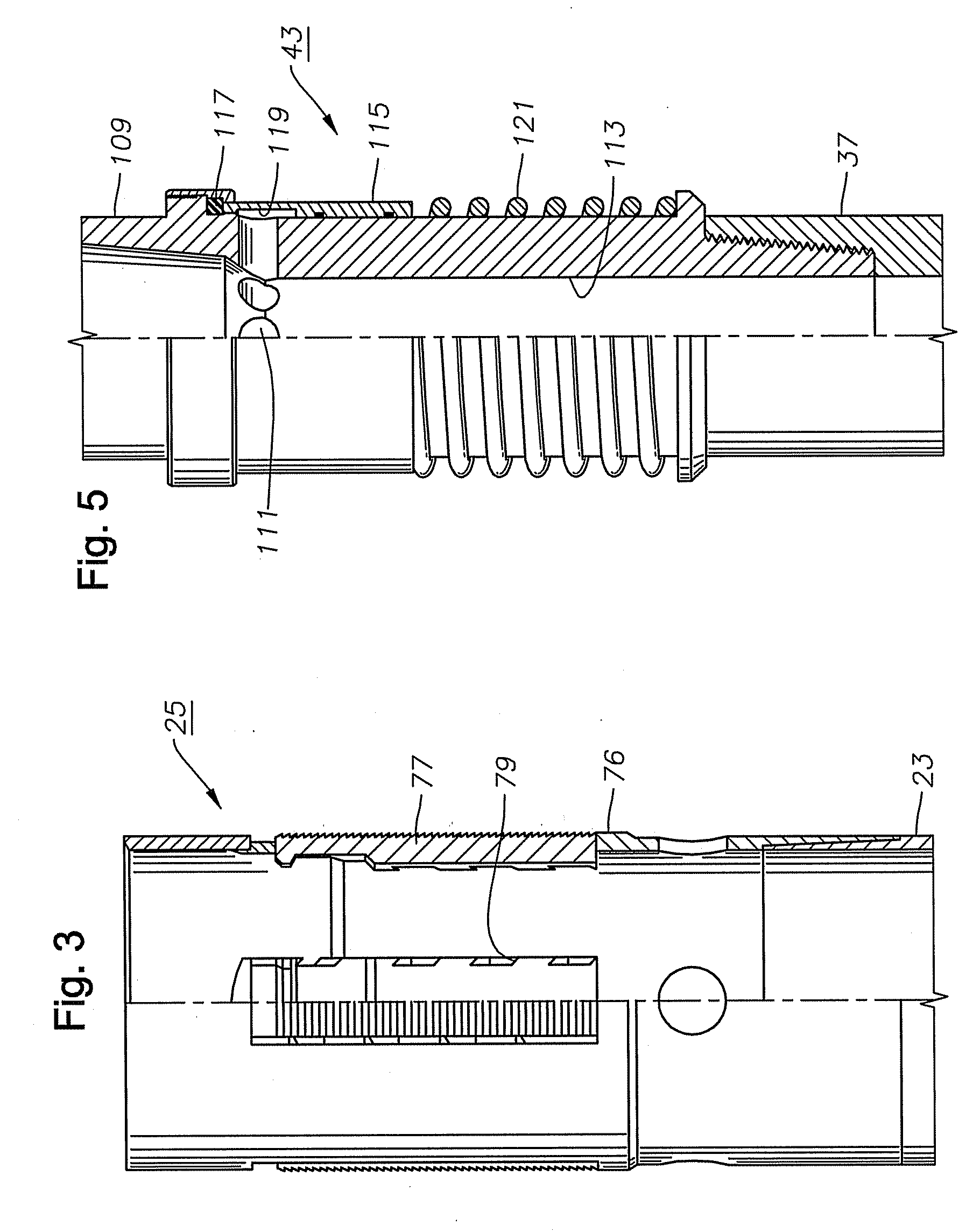
[0030]Referring to FIG. 1, a well is shown having a casing 11 that is cemented in place. An outer string 13 is located within casing 11 and extends below to an open hole portion of the well. In this example, outer string 13 is made up of a drill shoe 15 on its lower end that may have cutting elements for reaming out the well bore. A tubular shoe joint 17 extends upward from drill shoe 15 and forms the lower end of a string of liner 19. Liner 19 comprises pipe that is typically the same type of pipe as casing, but normally is intended to be cemented with its upper end just above the lower end of casing 11, rather than extending all the way to the top of the well or landed in a wellhead and cemented. The terms “liner” and “casing” may be used interchangeably. Liner 19 may be several thousand feet in length.

[0031]Outer string 13 also includes a profile nipple or sub 21 mounted to the upper end of liner 19. Profile nipple 21 is a tubular member having grooves and recesses formed in it f...


PUM


Abstract

A method of drilling a well and installing a liner includes assembling concentric inner and outer strings of tubulars. A drill bit is located at the lower end of the inner string and a liner with a liner hanger makes up part of the outer string. The inner and outer strings may be rotated in unison to drill the well. At a selected depth, the operator sets the liner hanger and retrieves the inner string. The operator lowers a packer and a cement retainer on a string of conduit. The packer engages the liner hanger and the cement retainer is conveyed to the lower end of the liner. The cement retainer prevents cement in the outer annulus from flowing back up the string of conduit. The operator manipulates the conduit to set the packer.

Description

CROSS-REFERENCE TO RELATED APPLICATION[0001]This application is a continuation-in-part of Ser. No. 12 / 238,191, filed Sep. 25, 2008, which claimed priority to provisional application Ser. No. 60 / 977,263, filed Oct. 3, 2007.FIELD OF THE INVENTION[0002]This invention relates in general to oil and gas well drilling while simultaneously installing a liner in the well bore.BACKGROUND OF THE INVENTION[0003]Oil and gas wells are conventionally drilled with drill pipe to a certain depth, then casing is ran and cemented in the well. The operator may then drill the well to a greater depth with drill pipe and cement another string of casing. In this type of system, each string of casing extends to the surface wellhead assembly.[0004]In some well completions, an operator may install a liner rather than an inner string of casing. The liner is made up of joints of pipe in the same manner as casing. Also, the liner is normally cemented into the well. However, the liner does not extend back to the w...

Claims


Application Information

Patent Timeline
Patent Type & Authority Applications(United States)
IPC IPC(8): E21B7/00E21B19/00E21B3/00
CPCE21B7/20E21B33/14E21B33/04E21B10/64
Inventor ERIKSEN, ERIK P.BROUSE, MICHAEL
Owner SCHLUMBERGER TECH CORP
Learn More