Two-axis magnetic field sensor

a magnetic field and sensor technology, applied in the field of bearing sensors, can solve the problems of inability to eliminate the influence of external magnetic fields, inaccurate bearing angles, and low price, and achieve the effect of simple small-scale structure and low pri

Inactive Publication Date: 2009-04-30
HITACHI METALS LTD
View PDF7 Cites 30 Cited by
  • Summary
  • Abstract
  • Description
  • Claims
  • Application Information

AI Technical Summary

Benefits of technology

[0024]In the present invention, the plane coil in plural shapes of almost right isosceles triangles or an almost rectangular shape is formed on a single plane so that the two-axis magnetic field sensor can measure a magnetic field, such as geo-magnetism, by applying a biasing magnetic field and simultaneously canceling an external offset magnetic field, after applying a reset magnetic field to the magneto-resistance elements. Also, because of the plane coil formed on a single plane, a magnetic field sensor with a simple small-sized structure can be provided for a low price. Furthermore, the two-axis magnetic field sensor according to the present invention can be applied for a bearing sensor, a current sensor, and other sensors for a weak magnetic field.

Problems solved by technology

In determination of a bearing based on geo-magnetism measured by a magnetic field sensor, external magnetic fields other than the geo-magnetism are a cause of bearing errors.
If there are external magnetic fields other than the geo-magnetism upon the detection, the magnetic field measured by the magnetic field sensor results in a compound magnetic field of the geo-magnetism and the external magnetic fields, which means that the calculated angle is not an accurate bearing angle.
However, it is impossible to eliminate the influence of the external magnetic fields.

Method used


Image

  • Two-axis magnetic field sensor
  • Two-axis magnetic field sensor
  • Two-axis magnetic field sensor

Examples


example 1

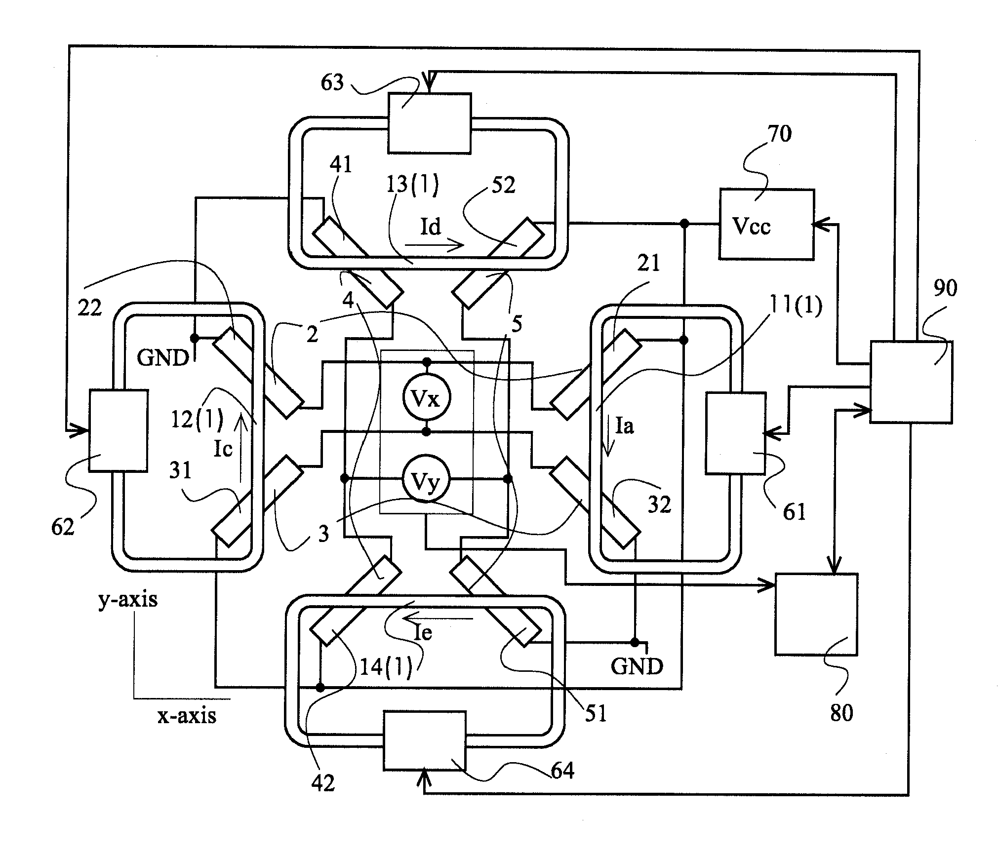
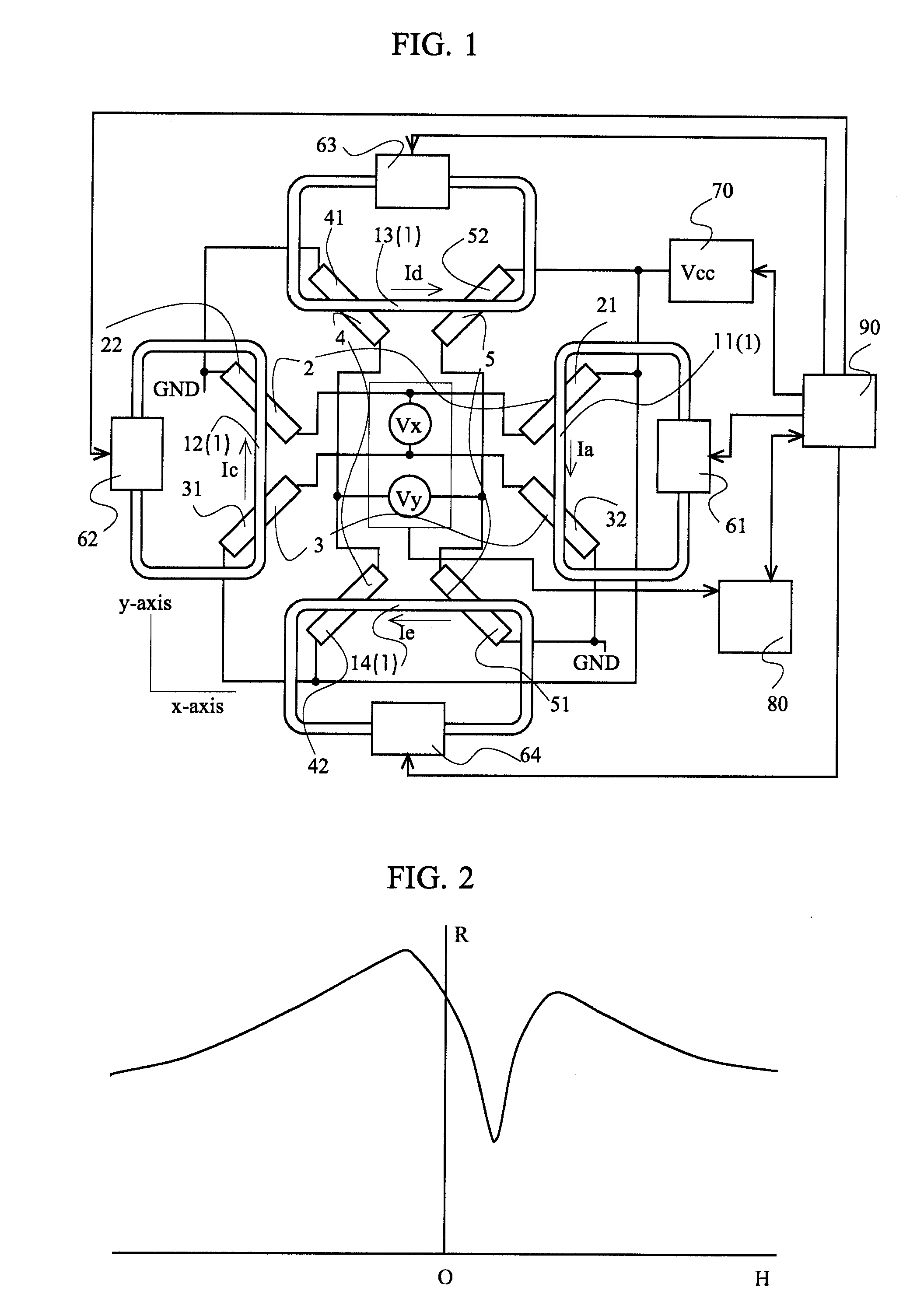
[0047]FIG. 1 is a schematic diagram of a two-axis magnetic field sensor of EXAMPLE 1 according to the present invention. The two-axis magnetic field sensor in EXAMPLE 1 has a plane coil 1 and four pairs of magneto-resistance elements 2, 3, 4, 5 provided on a plane adjacent to the plane coil and parallel to the plane coil. The plane coil 1 is composed of two first conductors 11, 12 parallel to each other and two second conductors 13, 14 that are perpendicular to the first conductors 11, 12 and parallel to each other. The four pairs of the magneto-resistance elements are composed of a pair of first magneto-resistance elements 2, a pair of second magneto-resistance elements 3, a pair of third magneto-resistance elements 4, and a pair of fourth magneto-resistance elements 5. The pair of the first magneto-resistance elements 2 includes a magneto-resistance element 21 having a longitudinal direction crossing only one of the two first conductors 11, 12 (e.g. the first conductor 11) and a m...

example 2

[0074]FIG. 6 is a schematic diagram showing a two-axis magnetic field sensor of EXAMPLE 2 in the present invention. The two-axis magnetic field sensor has a plane coil 1a and four pairs of magneto-resistance elements 2, 3, 4, 5 provided on a plane adjacent to the plane coil 1a and parallel to the plane coil 1a. The plane coil 1a is composed of right isosceles triangle plane coils 1a′, 1a″ whose hypotenuses are opposite to each other. The right isosceles triangle plane coils 1a′, 1a″ form a square plane coil with the hypotenuses as a diagonal line. Thus formed square plane coil 1a has two parallel first conductors 11, 12 and two parallel second conductors 13, 14 arranged perpendicular to the first conductors 11, 12. The positional relationship of the four pairs of the magneto-resistance elements and the conductors of the plane coil 1a are the same as in EXAMPLE 1 and their description is not reiterated.

[0075]The right isosceles triangle plane coils 1a′, 1a″ are wound in the same dire...

example 3

[0090]Measurement of a bearing and calculation of a magnetic field by a two-axis magnetic field sensor with external offset magnetic fields present can be performed by plane coils having right-angle apexes opposite to each other in EXAMPLE 3 in substantially the same manner as those by the square plane coil formed by arranging the hypotenuses of the two right isosceles triangles so as to be opposite to each other in EXAMPLE 2, and therefore their descriptions will not be reiterated.

[0091]FIG. 7 is a schematic diagram of the two-axis magnetic field sensor according to EXAMPLE 3 of the present invention. The two-axis magnetic field sensor has two parallel right isosceles triangle plane coils 1b′, 1b″ provided adjacent to a plane in which magneto-resistance elements are provided and parallel to the plane. In the plane of the magneto-resistance elements, magneto-resistance elements 21, 22, 31, 32, 41, 42, 51, 52 are provided.

[0092]The right isosceles triangle plane coil 1b′ and the righ...


PUM


Abstract

Disclosed is a small-sized two-axis magnetic field sensor having a function to cause a magnetic field canceling an external offset magnetic field. The two-axis magnetic field sensor contains a plane coil disposed on a plane and four sets of magneto-resistance element pairs on a plane parallel to the plane coil. The plane coil includes at least two pairs of parallel conductors, and two magneto-resistance elements cross only a single conductor of the coil. A current for canceling the external offset magnetic field is determined in advance, and while a DC current that causes total magnetic fields of biasing magnetic fields plus a magnetic field for canceling the external offset magnetic field flows through the coil, intermediate potential outputs from the magneto-resistance element pairs are detected to measure a magnetic field direction, such as geo-magnetism.

Description

TECHNICAL FIELD[0001]The present invention relates to a bearing sensor using magneto-resistance elements and, in particular, to a two-axis magnetic field sensor measuring a bearing while applying a biasing magnetic field to the magneto-resistance elements.BACKGROUND ART[0002]A magnetic field sensor measuring a bearing using magneto-resistance elements is disclosed in Patent Document 1. The magnetic field sensor is composed of an almost square plane coil formed on a plane substrate and four pairs of magneto-resistance elements crossing sides of the coil at a predetermined angle. By feeding a DC current to the plane coil, a reset magnetic field that magnetically saturates the magneto-resistance elements to a sufficient level and an appropriate magnetic field (biasing magnetic field) required upon measurement can be applied. In this case, the same amount of the reset or biasing magnetic field can be simultaneously applied in four directions: X direction; −X direction; Y direction; and ...

Claims


Application Information

Patent Timeline
Patent Type & Authority Applications(United States)
IPC IPC(8): G01R33/02
CPCG01C17/38G01R33/096G01R33/09G01R33/0005
Inventor ABE, YASUNORIONO, TOMOKINIHEI, YUJI
Owner HITACHI METALS LTD
Why Eureka
Try Eureka