Transformer for power supply

a transformer and power supply technology, applied in transformers/inductance details, inductances, electrical devices, etc., can solve the problems of reducing the magnetic coupling between the primary winding b>111/b> and the secondary winding b>112/b>, reducing the sound pressure level of buzzing noise, and reducing the sound pressure of buzzing noise. , the effect of reducing the sound pressure of buzzing nois

Inactive Publication Date: 2009-04-30
TAIYO YUDEN KK
View PDF3 Cites 19 Cited by
  • Summary
  • Abstract
  • Description
  • Claims
  • Application Information

AI Technical Summary

Benefits of technology

[0014]It is an object of an embodiment of the present invention to provide a transformer which is for use in a power supply and which uses switching pulses having a frequency lying in the audio frequency band, the transformer being characterized in that the level of sound pressure created by buzzing noise is reduced. It is another object of an embodiment of the invention to provide a transformer which is for use in a power supply and which can be manufactured stably in such a way that buzzing noises produced by individual products are less different in level of sound pressure.
[0022]An additional aspect of the transformer of the present invention for a power supply has the feature (3) described above. In addition, it is characterized in that (7) the spacer is higher in hardness than the adhesive. In consequence, the resonance point of vibrations of the core subassembly shifts toward higher frequency side. As a result, the sound pressure level of buzzing noise can be reduced. In addition, variations in sound pressure among products can be reduced.

Problems solved by technology

Confirmation of the level of sound pressure produced by each individual product has presented problems.
Consequently, confirmation of the level of sound pressure produced by each individual product has presented problems.
There is another problem that the magnetic coupling between the primary winding 111 and secondary winding 112 decreases.

Method used


Image

  • Transformer for power supply
  • Transformer for power supply
  • Transformer for power supply

Examples


example 1

[0098]The transformer 10 of the first embodiment of the present invention has the structure as already described in the first embodiment.

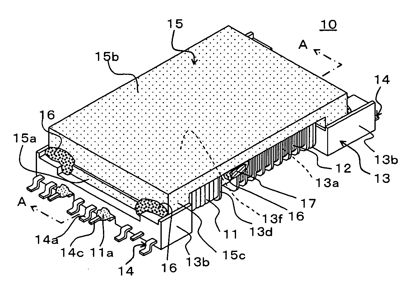
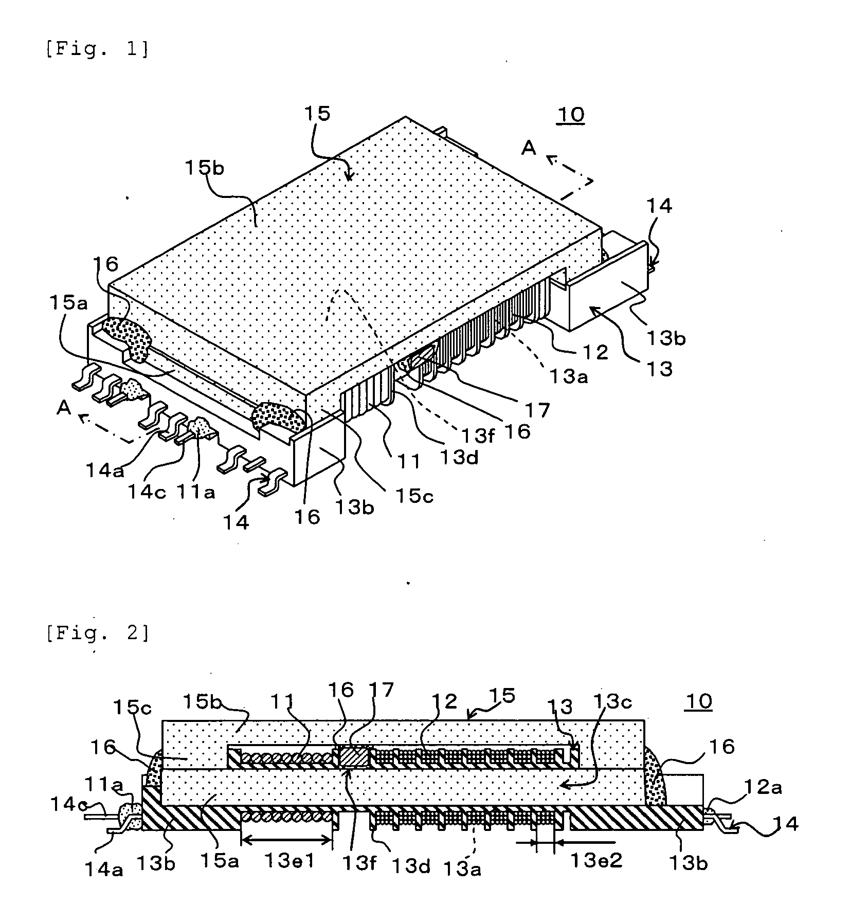
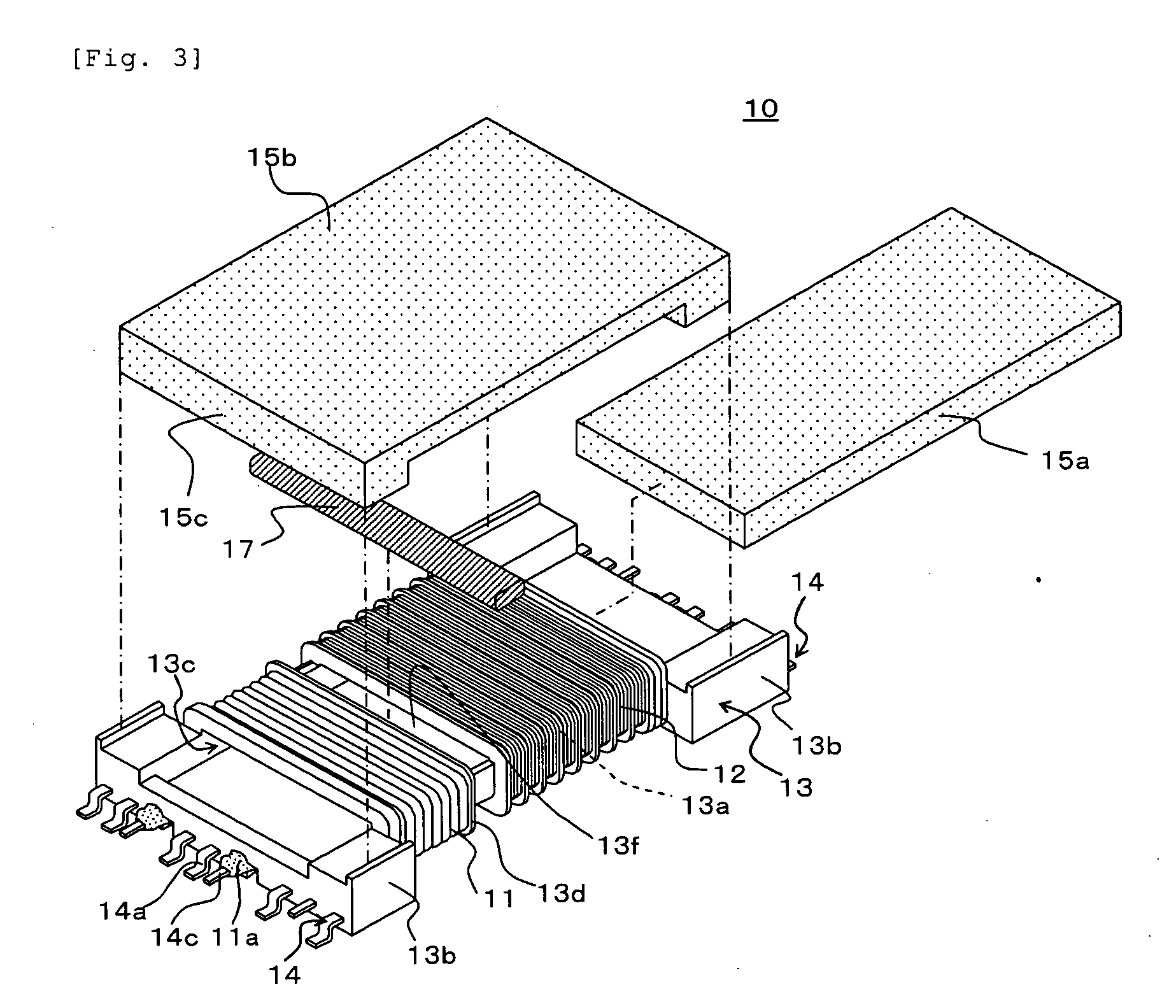
[0099]As shown in FIGS. 1-3, the transformer 10 of the present embodiment has the primary winding 11, the secondary winding 12, the bobbin 13 having separate portions on which the primary winding 11 and secondary winding 12 are respectively wound, and a core subassembly 15 mounted in the bobbin 13. The bobbin 13 is made of a liquid crystal polymer. The core subassembly 15 is made of an Mn—Zn based ferrite for magnetically coupling the primary winding 11 and secondary winding 12.

[0100]In particular, the bobbin 13 has the cylindrical portion 13a and a pair of bases 13b mounted on the opposite ends of the cylindrical portion 13a. The cylindrical portion 13a is provided with the magnetic core insertion hole 13c, and has a wire winding area. The wire winding area is partitioned into plural regions by the middle guard 13d. Plural terminals 14 are mounted...

example 2

[0106]The transformer of the second embodiment of the present invention for use in a power supply is similar to Example 1 described above except that the I-shaped core 15a inside the magnetic core insertion hole 13c and the U-shaped core 15b located outside the hole 13c are bonded to each other only with an epoxy resin based adhesive similar to the foregoing adhesive without using the spacer 17 of Example 1.


PUM

PropertyMeasurementUnit
heightaaaaaaaaaa
lengthaaaaaaaaaa
thicknessaaaaaaaaaa

Abstract

A transformer for use in a power supply has a primary winding, a secondary winding, a bobbin on which the primary and secondary windings are separately wound, and a core subassembly mounted in the bobbin. An opening is formed in the cylindrical portion of the bobbin, and an inside core in the magnetic core insertion hole and an outside core located outside the hole are adhesively bonded together via a spacer through the opening in the cylindrical portion.

Description

BACKGROUND OF THE INVENTION[0001]1. Field of the Invention[0002]The present invention relates to a transformer for use in a power supply and, more particularly, to a transformer which is for use in a power supply and which drives the backlight of a display panel of an electronic instrument, such as a liquid crystal TV or car navigational system, through an inverter.[0003]2. Description of the Related Art[0004]An electronic instrument such as a liquid crystal TV or car navigational system is equipped with a backlight using cold cathode fluorescent lamps or other electric-discharge lamps. To light up these electric-discharge lamps, inverter circuits have been used for obtaining high voltages from low-voltage DC power supplies.[0005]Referring to FIG. 12, a transformer 110 using a magnetic core 115 has been proposed as a transformer for a power supply used to drive an inverter circuit in patent reference 1. The magnetic core 115 is made of ferrite cores. In the transformer 110, the magn...

Claims


Application Information

Patent Timeline
Patent Type & Authority Applications(United States)
IPC IPC(8): H01F27/30
CPCH01F38/10H01F27/326H01F27/28H01F27/29H01F27/30
Inventor KOSUGI, AKIFUMIKIKUCHI, KICHIHOSAKA, YASUO
Owner TAIYO YUDEN KK
Why Eureka
Try Eureka