Smoothing motor speed during mixing

Active Publication Date: 2009-04-30
WHIRLPOOL CORP
View PDF38 Cites 21 Cited by
  • Summary
  • Abstract
  • Description
  • Claims
  • Application Information

AI Technical Summary

Benefits of technology

[0007]The invention relates to a method for smoothing the motor speed du

Problems solved by technology

The kneading of dough is one of the most difficult tasks that a mixing system performs because of the high forces required to knead the dough.
The high forces create high instantaneous loads on the motor, which can result in audible mechanical and motor noises, vibrations, variable motor

Method used


Image

  • Smoothing motor speed during mixing
  • Smoothing motor speed during mixing
  • Smoothing motor speed during mixing

Examples


Embodiment Construction

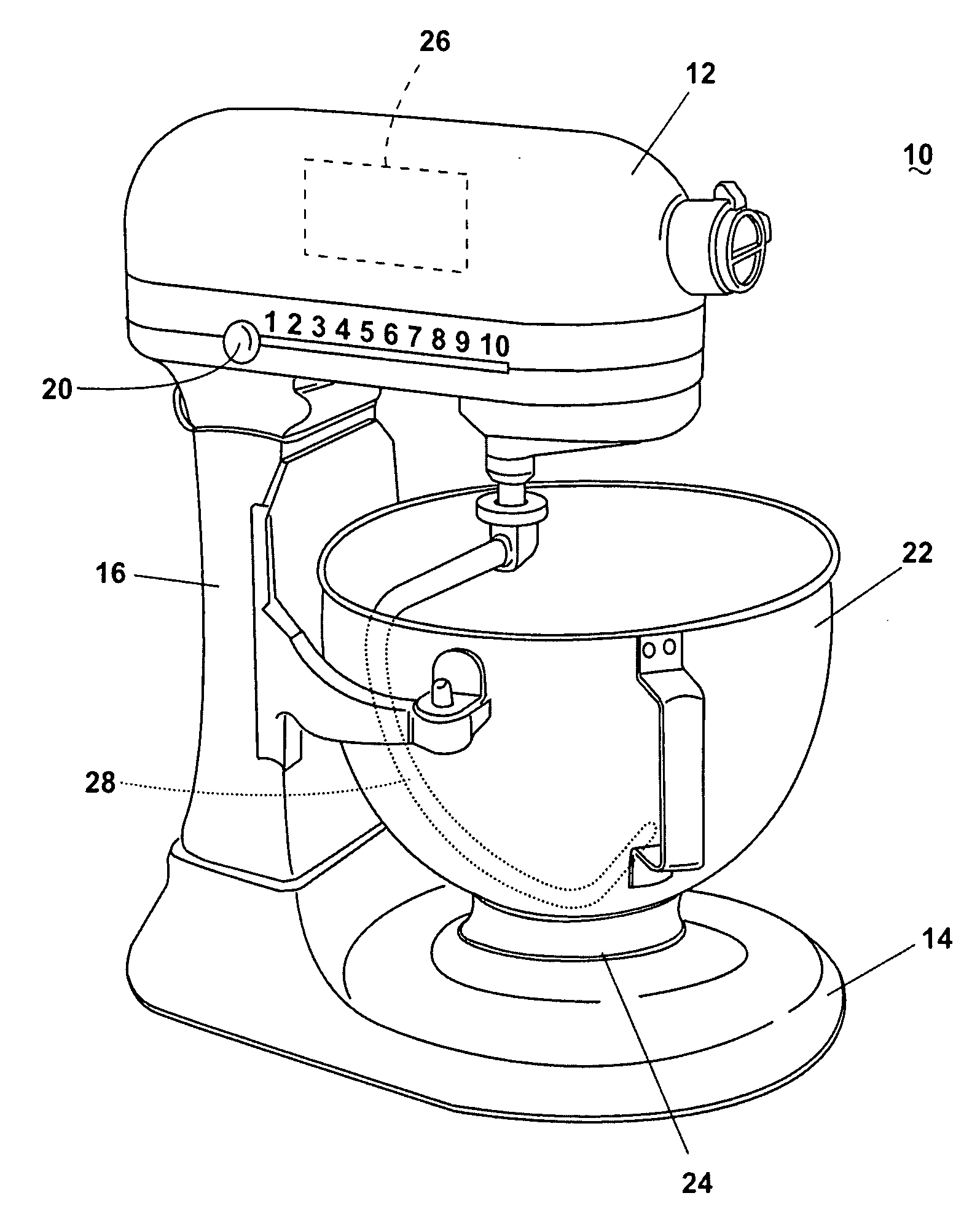
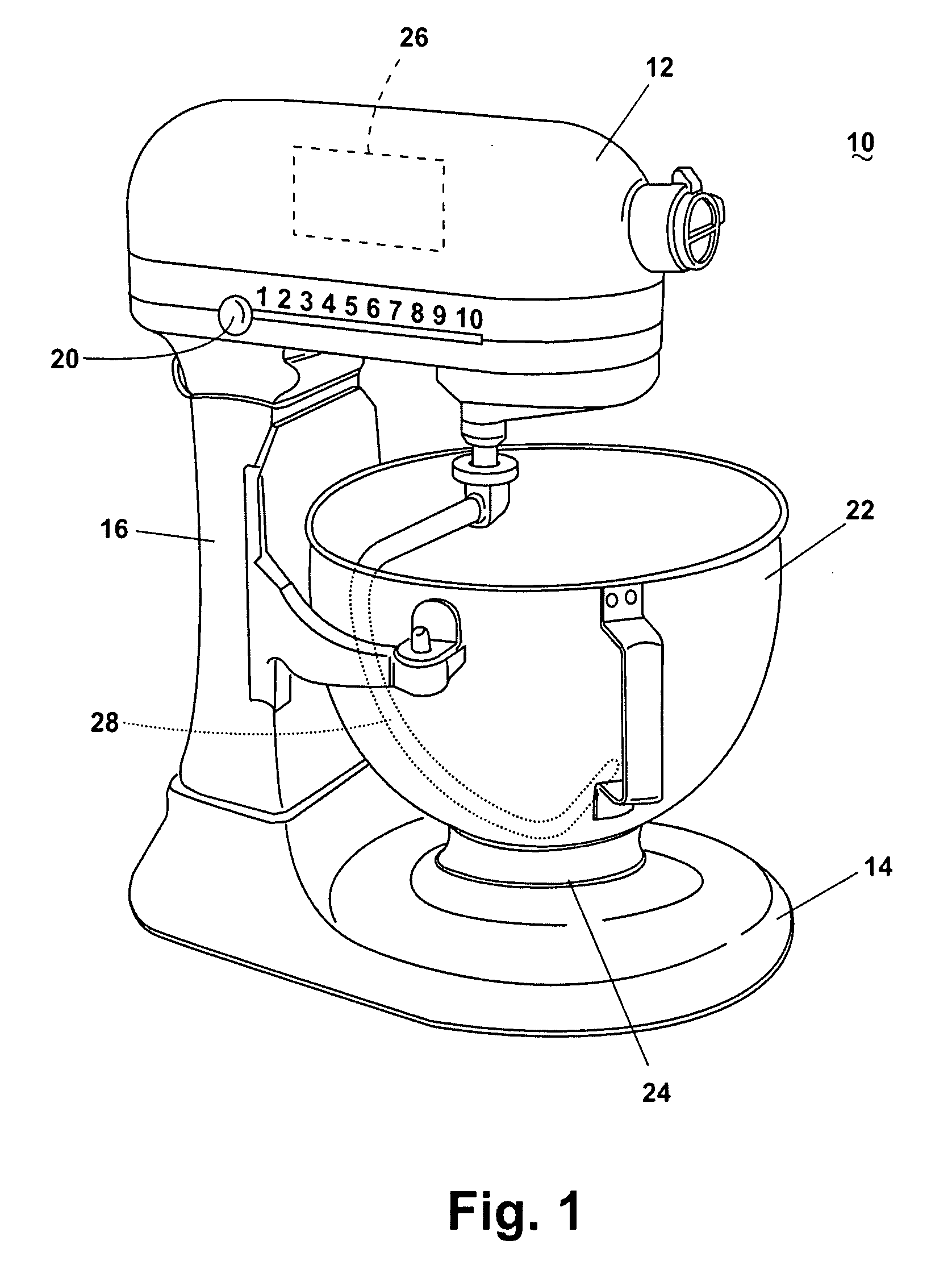
[0046]FIG. 1 illustrates a mixing system according to the invention in the form of a stand mixer 10 comprising a mixer head 12 and a base 14 having an upstanding pedestal portion 16 supporting the mixer head 12. The mixer head 12 contains a motor 26 which is shown in phantom. The mixing system includes several releasably attached mixing elements to be attached to the mixer head 12 for rotation thereby. A mixing element in the form of a dough hook 28 is shown partially in phantom. Other mixing elements include a wire whip and a flat beater among other things. The motor 26 provides motive power to the dough hook mixing elements. The dough hook is connected to the mixing system by a shaft and has an outermost portion which is used to mix the foodstuff. These mixing elements mix food and other items in a mixer bowl 22, which is supported on the base 14.

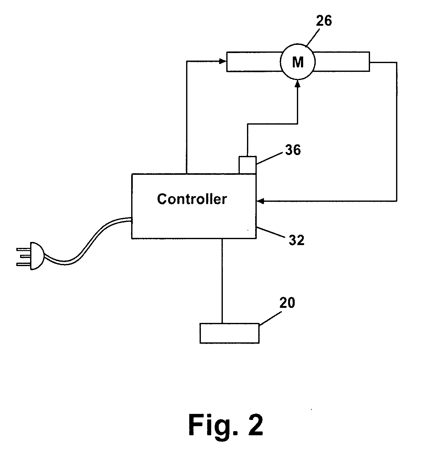
[0047]Referring also to FIG. 2, a controller 32 operably couples the motor 26 and a speed control knob 20 which is also mounted in the m...


PUM


Abstract

A mixing system comprising a bowl, mixing element and motor. A mixing element is located within the bowl and is driven by a motor to impart mechanical energy to the foodstuff being mixed upon contact. A method for increasing the power to the motor comprises introducing additional current in advance of instantaneous loading.

Description

BACKGROUND OF THE INVENTION[0001]1. Field of the Invention[0002]The invention relates to a method for identifying the foodstuff being mixed in a mixing system. The invention further relates to a method of operation the mixing system based on the foodstuff identified.[0003]2. Description of the Related Art[0004]Mixing systems are ubiquitous. Though there are a wide variety of such mixers in the market they can be generally classified into two broad categories. The first category includes a lightweight portable variety of mixer often used for small amounts of material, and which are often referred to as hand-held mixers. The second type is a stand mixer, which compared to the hand mixer typically has a larger motor and a fixed mixing bowl and is used for mixing larger quantities and also may be used for kneading bread dough and mixing other heavy foodstuffs efficiently. The stand mixers typically have a mixing device, such as a dough hook to knead the dough, which extends into the bow...

Claims


Application Information

Patent Timeline
IPC IPC(8): B01F15/00
CPCA21C1/02B01F7/00325H02P23/04B01F7/30B01F7/1605Y10S366/601B01F27/1126B01F27/805B01F27/95
Inventor CIANCIMINO, ROSARIOCONARD, WAYNE W.ZELVIS, NOAH DAVIDMILL, RYAN W.
Owner WHIRLPOOL CORP
Why Eureka
Try Eureka