In-situ determination of yield stress state of earth formations

a technology of yield stress and earth formation, which is applied in the field of earth formation investigation, can solve problems such as complete rock failure, and achieve the effect of accurate representation of elastic and plastic limits of octahedral stress and reliable estimation of in-situ properties

Active Publication Date: 2009-04-30
SCHLUMBERGER TECH CORP
View PDF11 Cites 43 Cited by
  • Summary
  • Abstract
  • Description
  • Claims
  • Application Information

AI Technical Summary

Benefits of technology

[0007]A novel technique is described herein allowing for a reliable estimation of in-situ rock yield stresses that help in determining an accurate representation of the elastic and plastic limits of octahedral stress. Since the stresses are a function of pressure and temperature, their in-situ estimation is particularly valuable to the successful drilling and production of a wellbore. Boreholes exhibit complex acoustic behavior complicating such a characterization of a formation from within. Many of the procedures and systems described herein can allow for a determination of the in-situ rock yield stress state using near-wellbore stress distributions and radial alterations in shear slowness in the cross-sectional plane of the wellbore trajectory. The yield stress state can be expressed in terms of the elastic limit and plastic limit of octahedral stress that helps in analyzing the viscoelastic deformation and creep flow in formations that cause borehole shrinkage or expansion that can lead to stuck pipe or heavy fluid loss while drilling. The in-situ estimate of the elastic limit of octahedral stress enables us to calculate a safe mud weight window for a chosen lithology interval.

Problems solved by technology

On the other hand, complete rock failure would occur if the in-situ octahedral stress exceeds the plastic limit of the material.

Method used


Image

  • In-situ determination of yield stress state of earth formations
  • In-situ determination of yield stress state of earth formations
  • In-situ determination of yield stress state of earth formations

Examples


Embodiment Construction

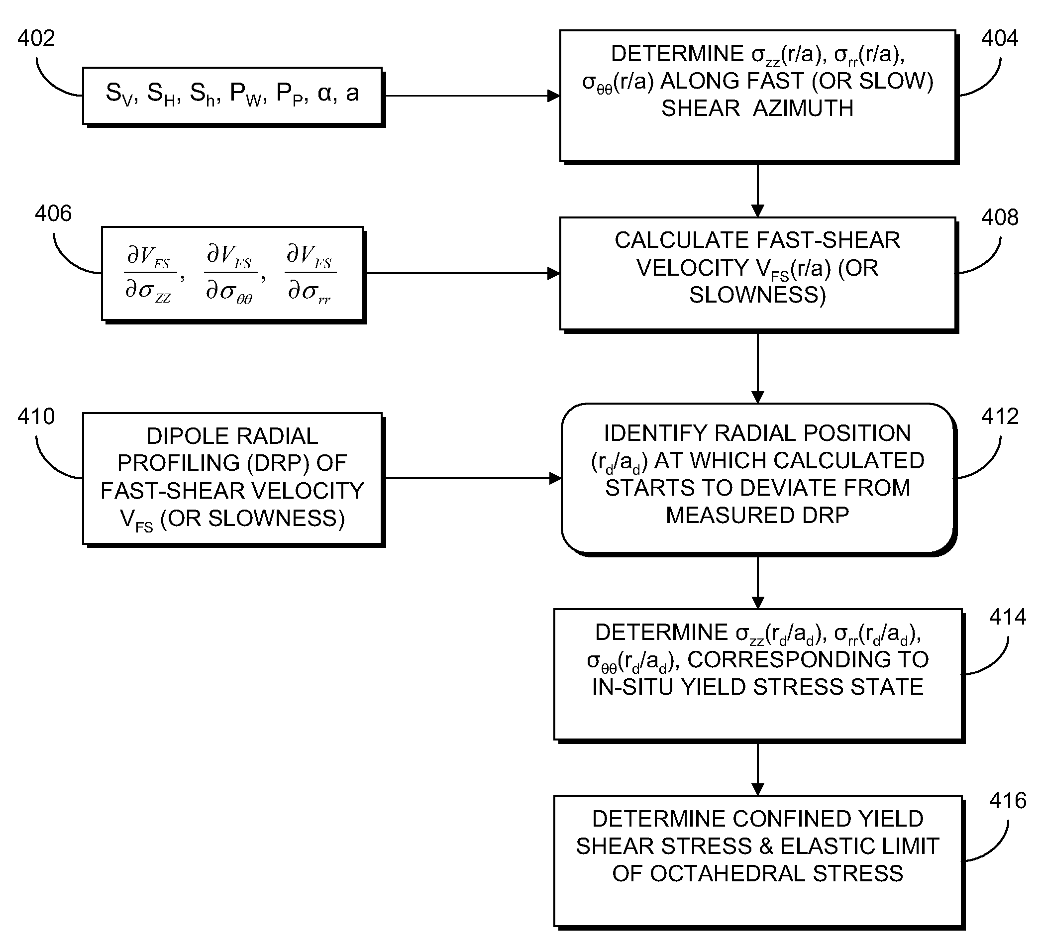
[0026]A new technique for estimating the in-situ rock yield stress state is described herein using radial profiling of shear slownesses along the maximum and minimum horizontal stress directions. The technique uses predicted values together with known formation stress parameters obtained from an inversion of cross-dipole dispersions. The in-situ yield stress state can then be used to calculate one or more of the elastic limits of octahedral stress and unconfined compressive strength. Such values are required for any reliable wellbore stability analysis.

[0027]One of the most important inputs to the wellbore stability analysis during and after drilling is an estimate of in-situ rock yield stress state or rock strength. The yield stress state can be used to calculate the octahedral stress threshold that helps in estimating a safe mud weight or wellbore pressure range to avoid large fluid loss or wall collapse. In particular, effects of viscoelastic deformation or creep flow in salt or ...


PUM


Abstract

Determination of in-situ rock yield stress state of a geological formation surrounding a borehole includes determining a profile for each of an axial effective, a radial effective, and a hoop effective stress within at least one axial plane containing a borehole axis. A predicted radial shear response radial profile is calculated from the effective stresses within the at least one axial plane. A measurement-based estimate of a shear response radial profile within the at least one axial plane is determined from measured data. A maximum radial distance at which a difference between the predicted and measurement-based shear response radial profiles is identified within the at least one axial plane as being greater than a difference threshold. The respective axial, radial, and hoop stresses, are determined at the identified maximum radial distance. The identified stresses are indicative of an in-situ yield stress state of the rock.

Description

REFERENCED PATENTS[0001]The present application incorporates the following patents by reference: U.S. Pat. No. 6,351,991, issued Mar. 5, 2002, entitled “Determining Stress Parameters of Formations from Multi-Mode Velocity Data,” and U.S. Pat. No. 6,611,761, issued Aug. 26, 2003 for “Sonic Well Logging for Radial Profiling,”FIELD OF THE INVENTION[0002]The present invention relates generally to the field of investigation of Earth formations and, more particularly, to determination of in-situ properties of Earth formations using sonic well logging techniques.BACKGROUND OF THE INVENTION[0003]Drilling through viscoelastic salt, shale and diatomite formations is a major challenge to avoid uncontrolled borehole shrinkage or expansion that can lead to stuck pipe or heavy fluid loss. Viscoelastic deformation or creep flow of material occurs whenever the octahedral stress exceeds its elastic limit that strongly depends on confining pressure as well as temperature. Rock failure occurs when the...

Claims


Application Information

Patent Timeline
Patent Type & Authority Applications(United States)
IPC IPC(8): G01V1/28G01V1/40
CPCG01V1/50E21B49/006
Inventor SINHA, BIKASH K.
Owner SCHLUMBERGER TECH CORP
Why Eureka
Try Eureka