
Dynamic equalizer

a technology of equalizer and dynamic equalizer, which is applied in the direction of amplification control, electrical apparatus, stereophonic arrangments, etc., can solve the problems of system frequency equalization, speaker equalization alone is not adequate for high-end systems, and the physical limitations of electrical to acoustic transducers such as speakers and headphones can significantly affect the performance of an audio system

Inactive Publication Date: 2009-04-30
VNS PORTFOLIO LLC
View PDF2 Cites 163 Cited by
  • Summary
  • Abstract
  • Description
  • Claims
  • Application Information

AI Technical Summary

Benefits of technology

[0012]Simultaneous with the detection of the chirp tone received by the second transducer, similar transducers located near each of the other speakers that are not broadcasting the chirp tone, detect the chirp tone and record its arrival time. On completion of the amplitude equalization process the arrival time information stored in each of the speakers for each transmitted chirp are used to compute a map of precise speaker pl

Problems solved by technology

Electrical to acoustic transducers such as speakers and headphones have physical limitations that can significantly affect the performance of an audio system.
Such systems do not typically provide frequency equalization nor do they account for differences in phasing produced by speaker placement.
Speaker equalization alone is not adequate for high end systems; there is a need also to compensate for the frequency response artifacts introduced by the home theater room and its contents, depending on the disposition of the speakers.
Further, manual equalization during installation is highly inconvenient and difficult for the average home theater user, and expensive if required to be done by a trained technician, owing to the considerable number of speakers.

Method used


Image

  • Dynamic equalizer
  • Dynamic equalizer
  • Dynamic equalizer

Examples


Embodiment Construction

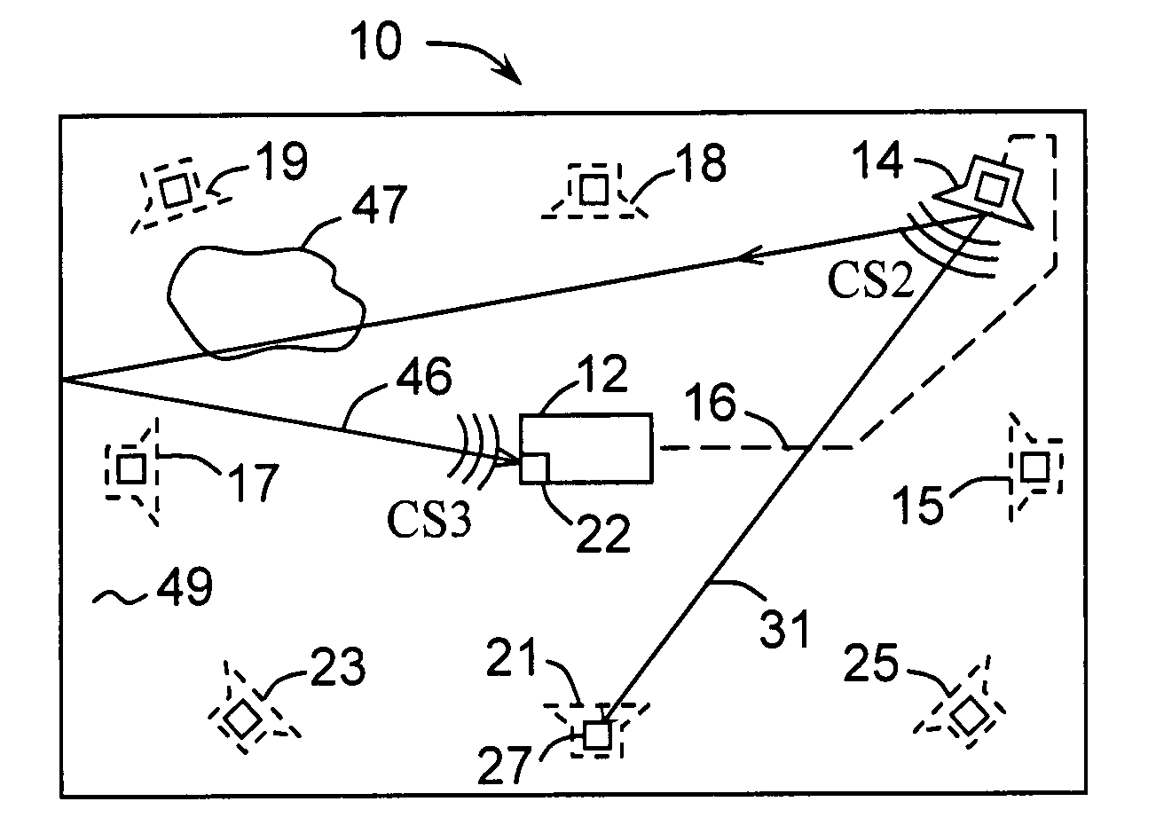
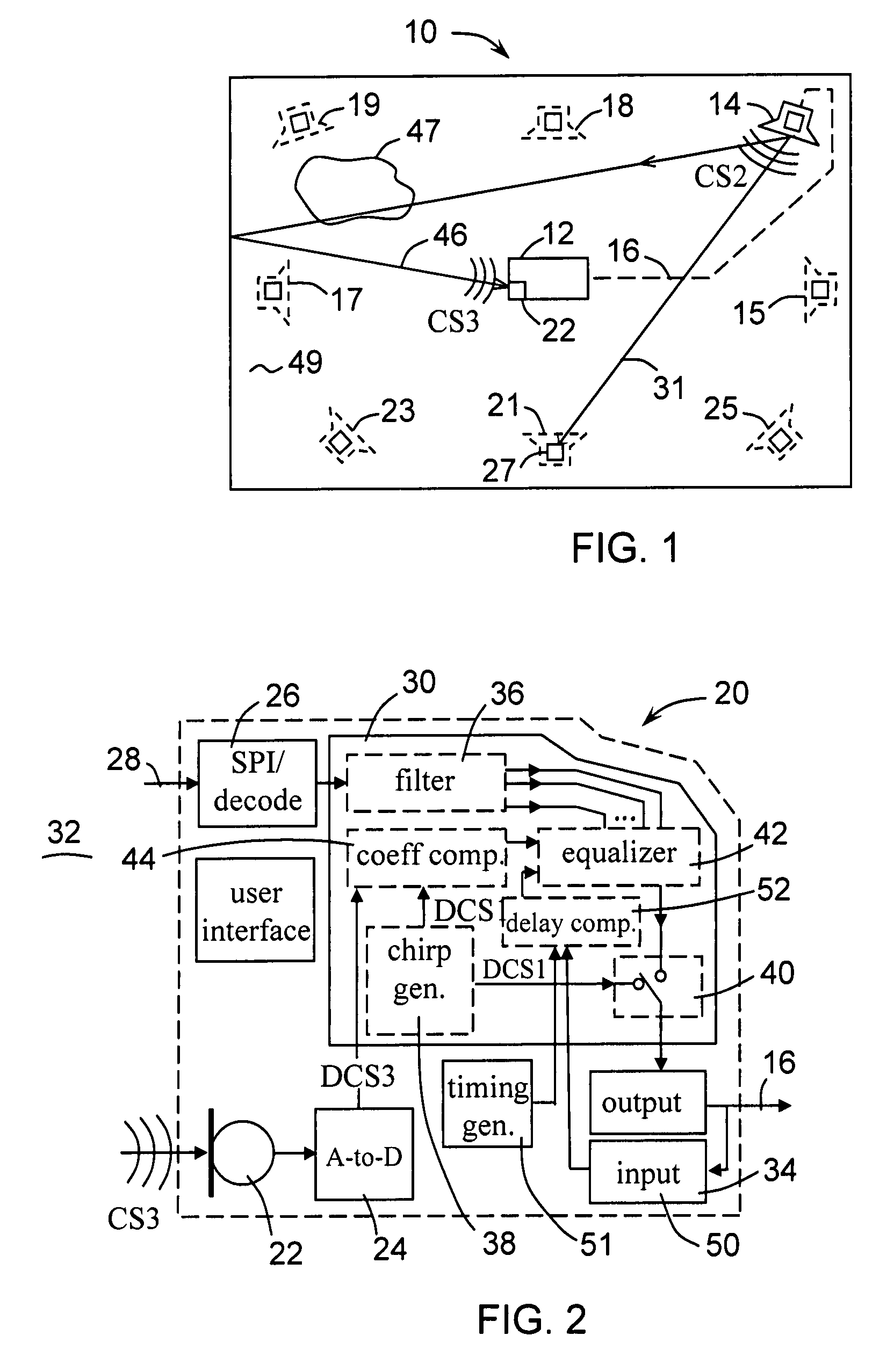
[0021]FIG. 1 shows a home theater room 10 with audio distribution module (ADM) 12 in a standard listening and viewing position near the center of the room. ADM 12 is connected to a sound generating transducer 14. Transducer 14 may be an electromagnetic or electrostatic speaker. The connection between ADM 12 and transducer 14 may be by a wire connection 16. It is also within the concept of the invention that transducer 14 be connected to ADM 12 by a wireless connection. It is also within the concept of the invention that the connection 16 between ADM 12 and transducer 14 may be bidirectional. Transducer 14 may be separately powered in some configurations and has appropriate attached circuits to accommodate a digital input signal from wire 16. In another embodiment, transducer 14 may be connected to ADM 12 with a direct analog audio drive over wire 16 without need of a separate power source. Transducer 14 is shown disposed in the conventional Right Front location. In a typical home th...


PUM


Abstract

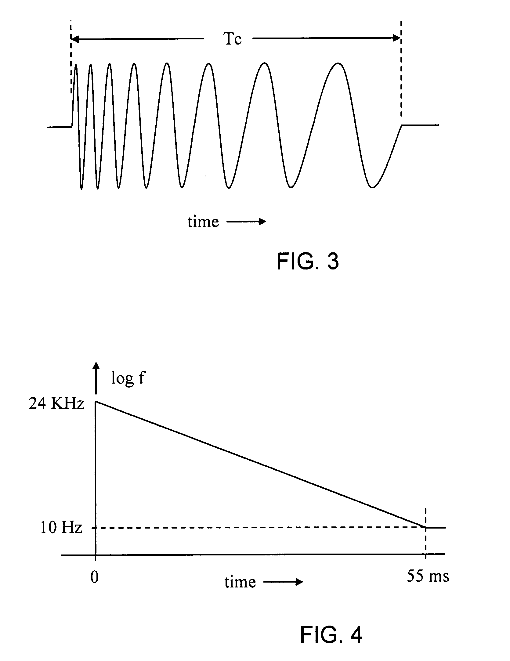
A dynamic equalization system 12 for use in audio reproduction systems. The apparatus includes a chirp tone generator 38 which produces a tone having multiple frequencies. The chirp tone is broadcast into the listening space 10 from a transducer 14. The broadcast chirp tone is monitored by a second transducer 22 at the listening position to produce a received chirp tone. The received tone and the original tone are compared in a coefficient computer 44 connected to a programmable equalizer 42. The equalizer 42 uses the signal from the coefficient computer to compensate for irregularities 47 in listening space 10 and transducer 14 to produce a substantially undistorted listening experience from source 28 in listening space 10. The first step of the method of the invention is generation of a chirp tone. The chirp tone includes multiple frequencies. The chirp tone is broadcast into the listening space from a transducer placed at the selected transducer position. The broadcast chirp tone is next monitored by a transducer at the listening position to produce a received chirp tone. The received tone is then compared to the generated chirp tone and differences noted. The differences are used to program an equalizer for correction of sound. The process is done for each position where a transducer is located. Finally, sound from a program source is routed through the equalizer to the transducers for a corrected sound.

Description

BACKGROUND OF THE INVENTION[0001]1. Field of Invention[0002]This invention relates generally to audio reproduction systems such as those used in home theater systems, and particularly to systems and method for equalizing the sound source apparatus.[0003]2. Description of the Prior Art[0004]A home theater audio system generally includes a source of an audio signal such as a DVD player. This signal is amplified and distributed to a plurality of audio reproduction devices such as speakers or headphones. A purpose of such systems is to provide high fidelity sound reproduction according to the traditional criteria of frequency response, dynamic range, and freedom from distortion. An additional purpose of such systems is to provide spatial acoustic realism. Spatial realism is defined as a perceived spatial distribution of sound that is in accordance with visual and other cognitive expectations commonly associated with the sounds. Electrical to acoustic transducers such as speakers and hea...

Claims


Application Information

Patent Timeline
IPC IPC(8): H04R5/02
CPCH03G5/165H04S7/301
Inventor SWAIN, ALLAN L.
Owner VNS PORTFOLIO LLC
Learn More