
Imaging device

a technology of a camera and an imager, which is applied in the direction of printers, camera focusing arrangement, exposure control, etc., can solve the problem of inhibiting rapid fire shooting at a high rate, and achieve the effect of high ra

Inactive Publication Date: 2009-04-30
SONY CORP
View PDF8 Cites 20 Cited by
  • Summary
  • Abstract
  • Description
  • Claims
  • Application Information

AI Technical Summary

Benefits of technology

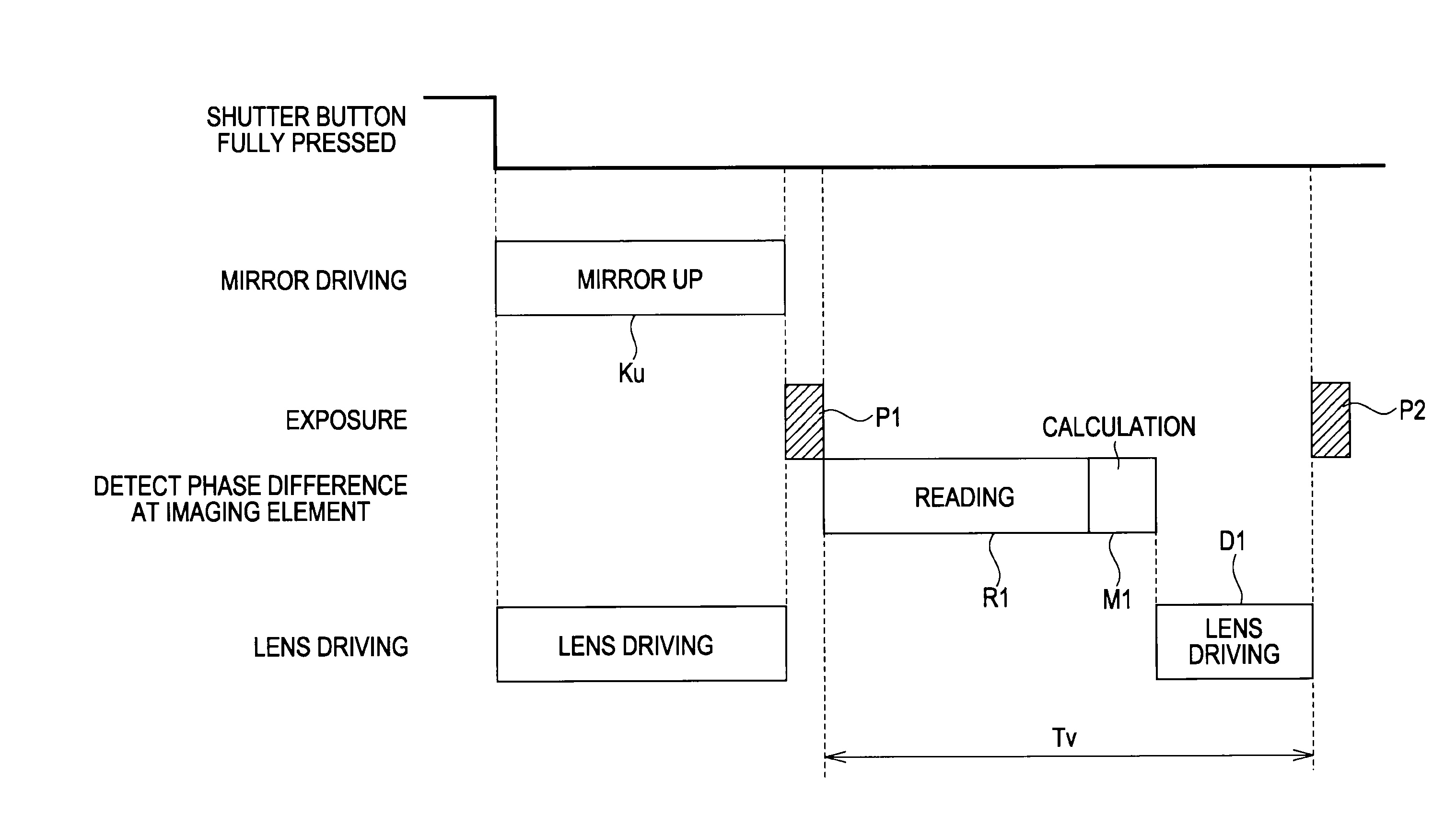
[0009]When a shutter button is full-pressed to start rapid-fire shooting, after an exposure (main exposure) P1 of an imaging surface, light from a subject is guided to the AF module by performing mirror-down driving Kd, and an exposure Pa for phase-difference detection is performed. After the exposure Pa, mirror-up driving Ku is performed, and reading Ra of exposure data from the AF module and a calculation process Ma for phase-difference AF are performed, and lens driving Da to an in-focus position is performed. In such operations during rapid-fire shooting, even if it is attempted to reduce a time interval Tw between the first time of main exposure P1 and the second time of main exposure P2, it is not possible to make the time interval Tw shorter than a total time taken for the mirror-down driving Kd, the mirror-up driving Ku, and the exposure Pa of the AF module. This inhibits increasing the rate of rapid-fire shooting.
[0012]According to the embodiment, during rapid-fire shooting performed by successively exposing an imaging element having two or more pairs of pixels arrayed along a predetermined direction, the pixels of each of the pairs receiving luminous fluxes from a subject coming through a pair of individually corresponding partial regions of an exit pupil of the shooting optical system, focus detection by a phase-difference detection method is performed on the basis of certain signals generated by the focus-detection pixel line on each occasion of exposure, and focus adjustment is performed during each interval of exposure. Accordingly, rapid-fire shooting at a high rate can be performed even in a case where phase-difference AF is performed during rapid-fire shooting.

Problems solved by technology

However, in phase-difference AF during rapid-fire shooting according to Japanese Unexamined Patent Application Publication No. 8-43914, since the mirror unit is driven to perform exposure in the AF module, rapid-fire shooting at a high rate is inhibited by the time taken for this operation.

Method used


Image

  • Imaging device
  • Imaging device
  • Imaging device

Examples


Embodiment Construction

External Configuration of an Imaging Device

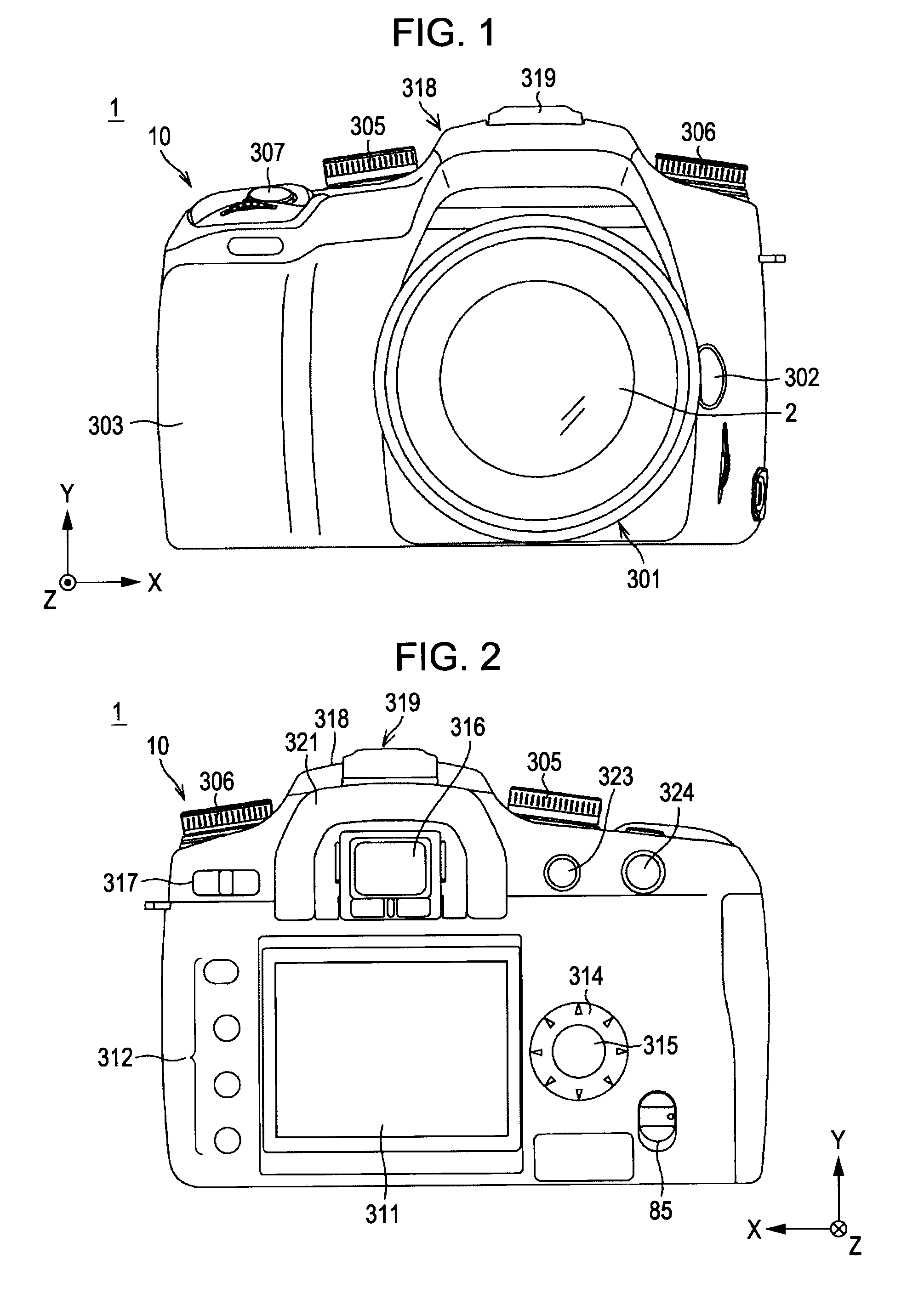
[0028]FIGS. 1 and 2 are illustrations showing the external configuration of an imaging device 1 according to an embodiment of the present invention, where FIG. 1 shows a front view and FIG. 2 shows a rear view.

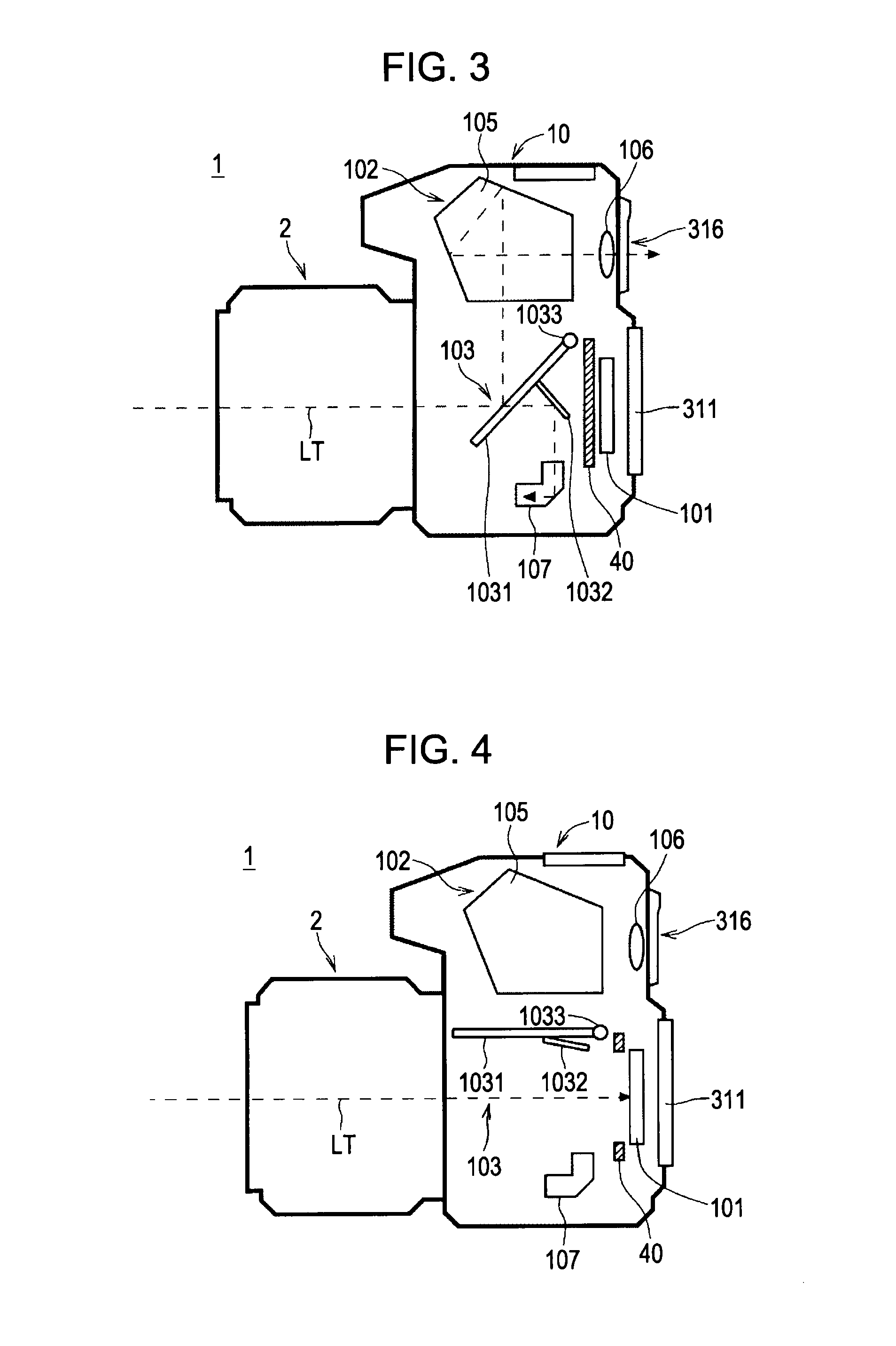
[0029]The imaging device 1 is configured as a single-lens reflex digital still camera. The imaging device 1 includes a camera body 10, and an exchange lens 2 as an imaging lens can be mounted on or dismounted from the camera body 10.

[0030]Referring to FIG. 1, provided on the front side of the camera body 10 are a mounting part 301 where the exchange lens 2 is mounted, provided substantially at the center of the front side, a lens exchange button 302 provided on the right side of the mounting part 301, a grip part 303 that allows a user to hold the imaging device 1, a mode setting dial 305 provided in an upper left part on the front side, a control-value setting dial 306 provided in an upper right part on the front side, and a shutter ...


PUM


Abstract

An imaging device having a shooting optical system, including an imaging element having a pixel array capable of generating image signals regarding light from a subject coming through the shooting optical system, and a focus-detection pixel line having pairs of pixels, the pixels of each of the pairs receiving luminous fluxes from the subject coming through a pair of individually corresponding partial regions of an exit pupil of the shooting optical system; a rapid-fire shooting unit configured to perform rapid-fire shooting to generate image signals at the pixel array on each exposure and to generate certain signals at the focus-detection pixel line; a focus detection unit configured to perform focus detection by a phase-difference detection method on the basis of the certain signals; and a focus adjustment unit configured to perform focus adjustment during each interval of the exposures on the basis of a result of focus detection.

Description

CROSS REFERENCES TO RELATED APPLICATIONS[0001]The present invention contains subject matter related to Japanese Patent Application JP 2007-280239 filed in the Japanese Patent Office on Oct. 29, 2007, the entire contents of which are incorporated herein by reference.BACKGROUND OF THE INVENTION[0002]1. Field of the Invention[0003]The present invention relates to an imaging device having a shooting optical system.[0004]2. Description of the Related Art[0005]In a single-reflex camera (imaging device), a mirror unit including a main mirror and a submirror that can be driven are provided, and when the mirror unit is moved down, light from a subject coming through a shooting lens is guided to a phase-difference-detection AF module (phase-difference AF module) and an optical finder, and when the mirror unit is moved up, light from the subject is guided to an imaging surface.[0006]In rapid-fire shooting by such a camera, the mirror unit is driven to move down and move up during each interval...

Claims


Application Information

Patent Timeline
Patent Type & Authority Applications(United States)
IPC IPC(8): G03B13/32
CPCG03B13/32H04N23/67H04N23/63
Inventor FUJII, SHINICHI
Owner SONY CORP
Learn More