
Speech intelligibility in telephones with multiple microphones

a technology of speech intelligibility and microphones, applied in the field of telephones, can solve the problems of difficult differentiation of inability of far-end users to decipher desired voice components against embedded background noise components, and inability to distinguish voice components from background noise components, etc., to achieve the effect of improving speech intelligibility and improving speech intelligibility

Active Publication Date: 2009-04-30
AVAGO TECH INT SALES PTE LTD
View PDF76 Cites 63 Cited by
  • Summary
  • Abstract
  • Description
  • Claims
  • Application Information

AI Technical Summary

Benefits of technology

[0013]The present invention is directed to improved speech intelligibility in telephones with multiple microphones. Embodiments of the present invention provide telephones and methods for improving speech intelligibility, for example, when a user is located in an environment having background noise.
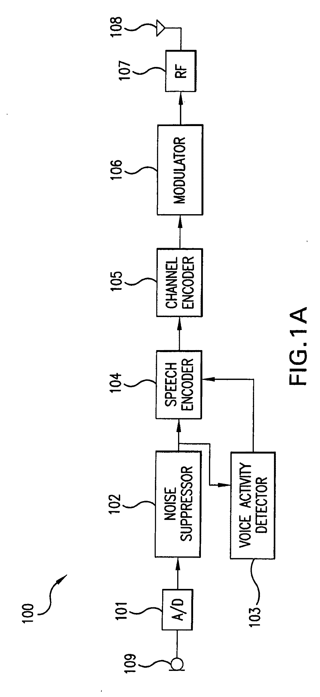
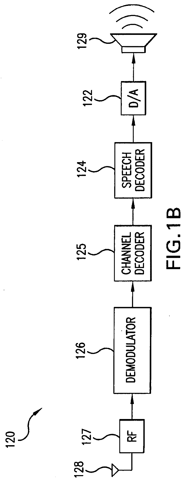
[0020]Another embodiment of the present invention provides a telephone for improving speech intelligibility when the telephone is used in an environment having background noise. The telephone includes a first microphone, a second microphone, a VAD, a receiver module, and a signal processor.

Problems solved by technology

However, the audio signal output by this microphone typically includes both a voice component and a background noise component.
As a result, the far-end user often has difficulty deciphering the desired voice component against the din of the embedded background noise component.
However, in practice, differentiating the voice component from the background noise component is difficult.
Furthermore, when a near-end user uses a telephone in a noisy environment, the far-end talker's voice can be difficult to understand due to the loud acoustic background noise of the noisy environment.
A common problem in this high background noise condition, however, is that when the near-end user starts to talk, his voice will often be treated as noise, with the far-end user's voice being amplified or otherwise modified accordingly in an attempt to overcome this supposed “noise”.
This can result in a shouting match between the near-end user and the far-end user.
At the very least, the loudness of the far-end user's voice may be modulated by the near-end user's voice, resulting in unnatural loudness fluctuation.
Although a VAD can be used for the near-end talker's voice, it is difficult to have reliable voice activity detection when the background noise is very loud.
Another problem is that the far-end talker may have a hard time understanding the near-end talker's voice since the near-end talker is in an environment with very loud background noise.

Method used


Image

  • Speech intelligibility in telephones with multiple microphones
  • Speech intelligibility in telephones with multiple microphones
  • Speech intelligibility in telephones with multiple microphones

Examples


first embodiment

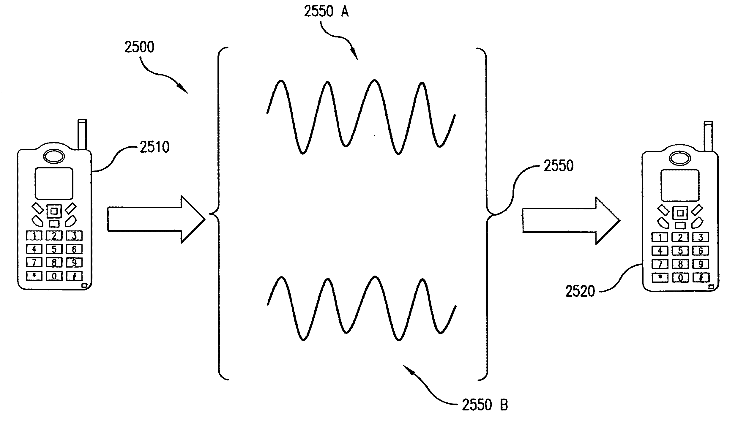
[0188]In the present invention, decoder 2670 is further configured to perform two functions: (i) time-align the signals received by receiver module 2660, and (ii) combine the time-aligned signals to produce the output signal. As is apparent from FIG. 21, due to the spatial separation of the microphones in a microphone array, a sound wave emanating from the mouth of a user may impinge upon each microphone in the array at different times. For example, with reference to FIG. 21, parallel wave fronts 2110 will impinge upon the left-most microphone of microphone array 2100 before it impinges upon the microphone separated by a distance d from the left-most microphone. Since there can be a time-delay with respect to when the sound waves impinge upon the respective microphones in microphone array 2610, there will be a corresponding time-delay with respect to the audio signals output by the respective microphones. Decoder 2670 of second wireless telephone 2520 can compensate for this time-de...

second embodiment

[0191]In the present invention, decoder 2670 of second wireless telephone 2520 is configured to perform the following functions. First, decoder 2670 is configured to detect a direction of arrival (DOA) of a sound wave emanating from the mouth of a user of first wireless telephone 2510 based on transmitted signals 2550 received by receiver module 2660 of second wireless telephone 2520. Decoder 2670 can determine the DOA of the sound wave in a similar manner to that described above with reference to FIGS. 21 through 24.

[0192]Second, decoder 2670, which as mentioned above may optionally include a DSP, is configured to adaptively combine the received signals based on the DOA to produce the output signal. By adaptively combining the received signals based on the DOA, decoder 2670 of second wireless telephone 2520 can effectively steer a maximum sensitivity angle of microphone array 2610 of first wireless telephone 2510 so that the mouth of the user of first wireless telephone 2510 is wit...

third embodiment

[0193]In the present invention, for each voice frame of the signals received by receiver module 2660, decoder 2670 of second wireless telephone 2520 is configured to perform the following functions. First, decoder 2670 is configured to estimate channel impairments (e.g., bit errors and frame loss). That is, decoder 2670 is configured to determine the degree of channel impairments for each voice frame of the received signals. For example, for a given frame, decoder 2670 can estimate whether the channel impairments exceed a threshold. The estimate can be based on signal-to-noise ratio (S / N) or carrier-to-interference ratio (C / I) of a channel, the bit error rate, block error rate, frame error rate, and or the like. Second, decoder 2670 is configured to decode a received signal with the least channel impairments, thereby producing the output signal for the respective voice frames.

[0194]By adaptively decoding the signal with the least channel impairments for the respective voice frames, ...


PUM


Abstract

The present invention is directed to improved speech intelligibility in telephones with multiple microphones. Such a telephone includes a first microphone, a second microphone, a voice activity detector (VAD), a receiver module, and a signal processor. The first microphone outputs a first audio signal, which comprises a voice component when a near-end user talks and a background noise component. The second microphone outputs a second audio signal. The VAD generates a voice activity signal responsive to a ratio between the first audio signal and the second audio signal. The voice activity signal identifies time intervals in which the voice component of the near-end user is present in the first audio signal. The receiver module receives a third audio signal, which comprises a voice component of a far-end user. The signal processor modifies the third audio signal responsive to the voice activity signal.

Description

CROSS REFERENCE TO RELATED APPLICATIONS[0001]This application is related to U.S. patent application Ser. No. 11 / 653,858 to Chen, entitled “Improved Channel Decoding for Wireless Telephones with Multiple Microphones and Multiple Description Transmission” and filed Jan. 17, 2007, which is a continuation-in-part of U.S. patent application Ser. No. 11 / 215,304 to Chen et al., entitled “Wireless Telephone with Multiple Microphones and Multiple Description Transmission” and filed Aug. 31, 2005, which is a continuation-in-part of U.S. patent application Ser. No. 11 / 135,491 to Chen, entitled “Wireless Telephone with Adaptive Microphone Array” and filed May 24, 2005, which is a continuation-in-part of U.S. patent application Ser. No. 11 / 065,131 to Chen, entitled “Wireless Telephone With Uni-Directional and Omni-Directional Microphones” and filed Feb. 24, 2005, which is a continuation-in-part of U.S. patent application Ser. No. 11 / 018,921 to Chen et al., entitled “Wireless Telephone Having Mul...

Claims


Application Information

Patent Timeline
IPC IPC(8): H04M1/00
CPCH04R3/005H04M1/6008
Inventor CHEN, JUIN-HWEY
Owner AVAGO TECH INT SALES PTE LTD
Learn More