Finger unit for robot hand and method of assembling the same

a robot hand and finger unit technology, applied in the direction of arms, manufacturing tools, gearing, etc., can solve the problems of poor meshing, bearing malfunction, and compromise of the cleanliness of the clean room

Active Publication Date: 2009-05-07
HARMONIC DRIVE SYST IND CO LTD +1
View PDF8 Cites 34 Cited by
  • Summary
  • Abstract
  • Description
  • Claims
  • Application Information

AI Technical Summary

Benefits of technology

[0009]It is an object of the present invention to provide a finger unit for a robot hand that is able to eliminate the incidence of such problems, and is of a lightweight and compact construction; and also to provide a method of assembling the same.
[0021]According to the present invention, the pair of bevel gears and the joint shaft that constitute the joint section of the finger unit are accommodated in a tubular housing whose forward end is closed. An opening in a rear end of the tubular housing is closed by a rotation actuator, which is fastened and secured to the tubular housing. Accordingly, foreign matter is prevented from entering from the outside into the mesh section and the rotating and sliding sections of the joint section. Lubricant is also prevented from being scattered outward from these sections. It is accordingly possible to produce a lightweight and compact finger unit for a robot hand, which is suitable for use in a place where thick powder dust is present and in a clean room.
[0029]According to this arrangement, the outer side of one of the shaft bearings for rotatably supporting the joint shaft is sealed using an oil seal, and the other bearing is shielded from the exterior by a cover member. The shaft bearing section is accordingly shielded from the exterior, whereby foreign matter can be reliably prevented from entering the shaft bearing section from the exterior, and lubricant or the like can be reliably prevented from being scattered from the shaft bearing section to the exterior. Moreover, the tasks associated with incorporating the joint shaft, the driven bevel gear, and the first and second bearings within the tubular housing can be performed straightforwardly via the large second opening.
[0032]According to the present invention, sections other than the driven bevel gear are covered by a small-diameter arcuate forward end section, and the finger body is allowed to swivel along the exterior surface thereof. Extraneous space within the tubular housing can accordingly be eliminated. Moreover, the finger body can be brought closer to the joint shaft, and the length of the swivel arm can accordingly be reduced. The load torque can be lowered, and thrust can be increased.
[0034]The finger unit of the robot hand having the above construction is readily assembled as described hereunder. Specifically, a method of assembling the finger unit for a robot hand of the present invention is characterized in comprising: incorporating the driven bevel gear along with the first and second bearings on the joint shaft; inserting and positioning these parts in the tubular housing via the second opening; screwing and securing the cover member on the second opening; mounting the oil seal; inserting, via the opening in the rear end of the tubular housing, a forward end section of the rotation actuator to which the driving bevel gear and shim plate have been attached, and causing the driving bevel gear to mesh with the driven bevel gear; and fastening and securing the rotation actuator to the tubular housing.
[0040]According to the finger unit of the robot hand of the present invention, the joint sections thereof are covered by tubular housings, and openings on the rear ends of these housings are closed by the forward end sections of the main bodies of the rotation actuators fastened and secured thereto. A finger unit comprising substantially sealed joint sections can accordingly be obtained. It is therefore possible to produce a lightweight and compact finger unit for a robot hand that is suitable for use in a place where thick powder dust is present and in a clean room. Moreover, using a shaft bearing fitted with a seal makes it possible to prevent powder dust from entering and lubricant or the like from scattering.

Problems solved by technology

A problem is presented in regard to the high likelihood that poor meshing will occur, a bearing will malfunction, or other adverse circumstances will arise.
In the case that a robot hand is used in a clean room, a lubricant that has been supplied or applied to the bearing sections and bevel gear meshing sections in the joint sections will be scattered, and a problem will be presented in that the cleanliness of the clean room will be compromised.

Method used


Image

  • Finger unit for robot hand and method of assembling the same
  • Finger unit for robot hand and method of assembling the same
  • Finger unit for robot hand and method of assembling the same

Examples


Embodiment Construction

[0048]A description shall be provided below with reference to the accompanying drawings for the multi-joint finger unit of the high-speed robot hand in which the present invention is employed.

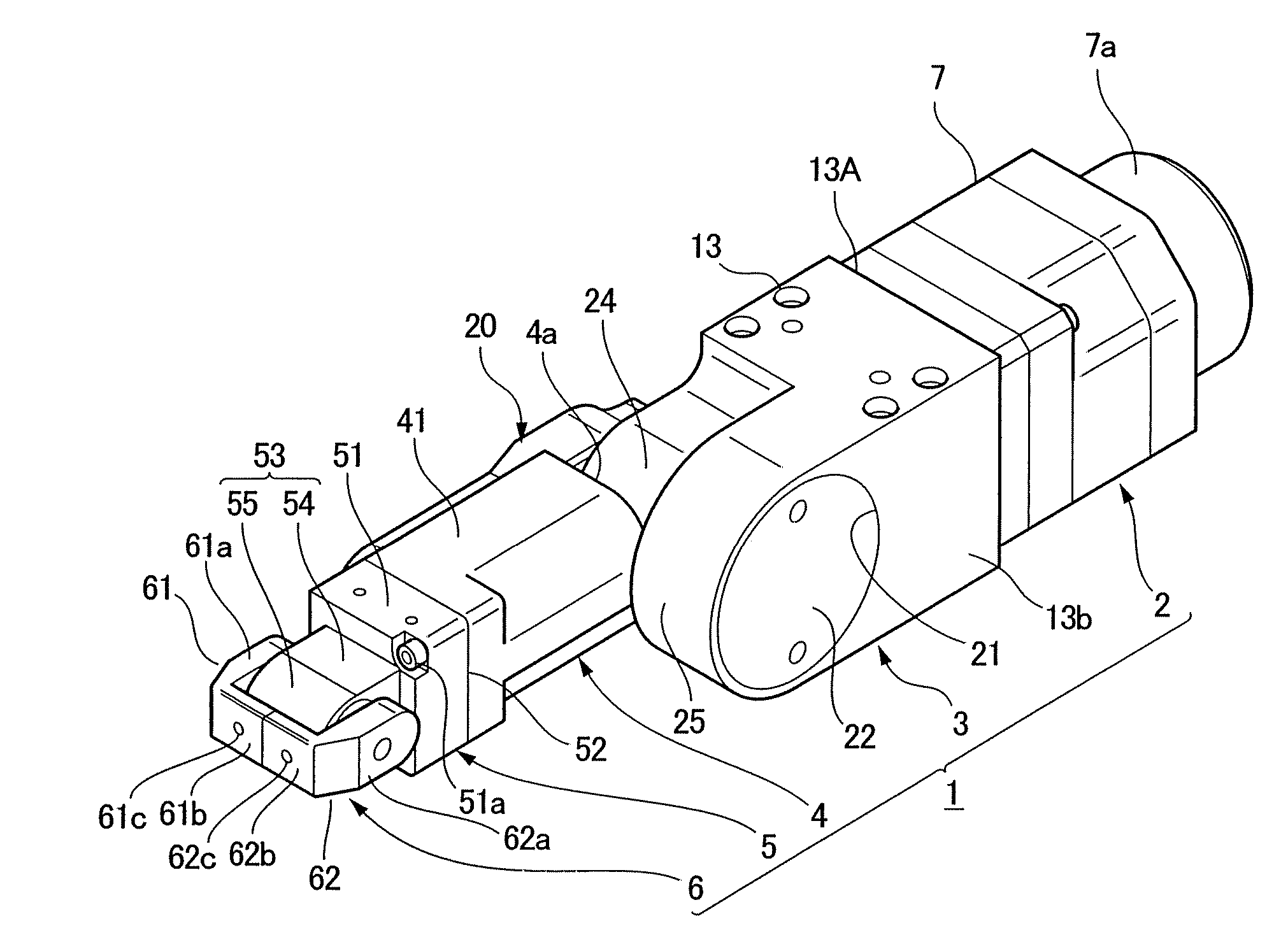
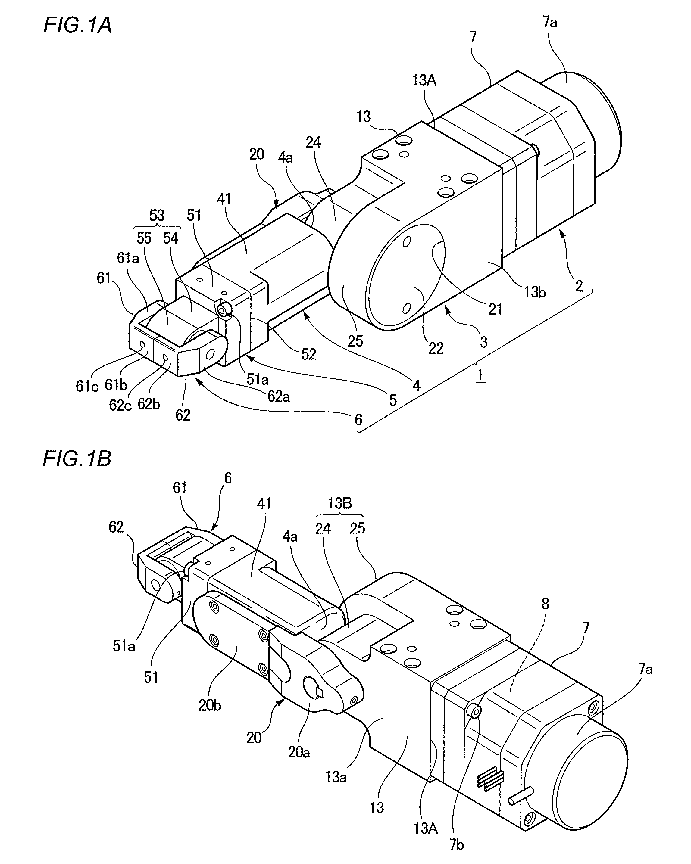
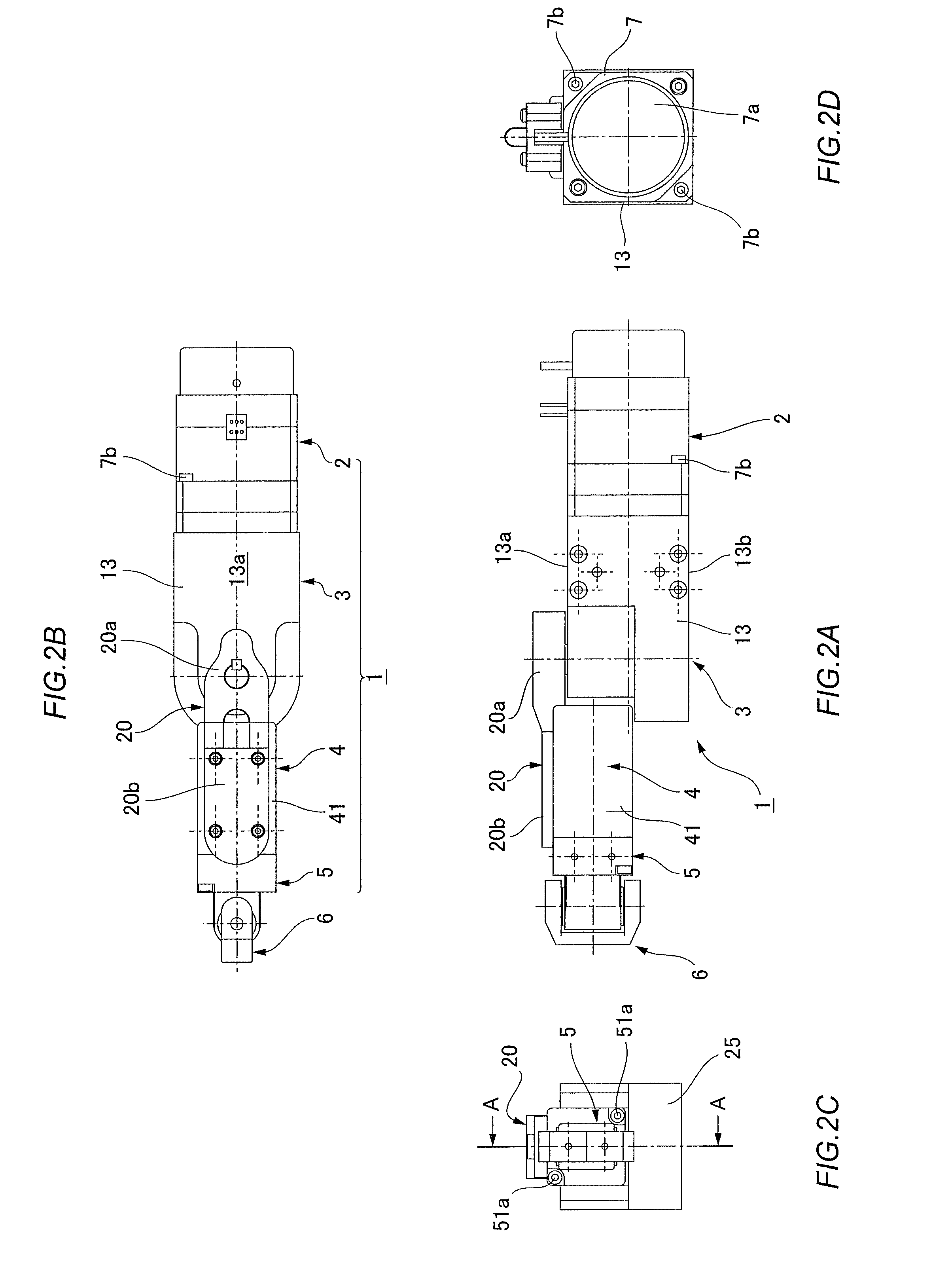
[0049]FIGS. 1A and 1B are exterior perspective views showing a front surface and rear surface of a multi-joint finger unit of a high-speed robot hand according to the present embodiment. FIGS. 2A through 2D are a plan view, lateral view, forward-wide end view, and rear-side end view of the multi-joint finger unit. FIG. 3 is a vertical sectional view showing FIG. 2C cut along line A-A.

[0050]A multi-joint finger unit 1 is a two-joint finger unit comprising a finger root 2; a first joint section 3 attached to a forward end of the finger root 2; a finger body section 4 attached to a forward end of the first joint section 3; a second joint section 5 attached to a forward end of the finger body section 4; and a fingertip section 6 attached to a forward end of the second joint section 5.

[0051]In the f...


PUM

PropertyMeasurementUnit
radiusaaaaaaaaaa
speedsaaaaaaaaaa
speedaaaaaaaaaa

Abstract

A multi-joint finger unit (1) has first and second joint sections (3, 5) constructed by using bevel gears. In each joint section (3, 5), the section where a driving bevel gear (10, 44) and a driven bevel gear (14, 56) mesh with each other and also a bearing section of a joint shaft (15, 57) are assembled in a tubular housing (13, 51) whose forward end is closed. Rear end openings (13A, 52) of the tubular housings (13, 51) are closed by a tubular housing (7) at a finger root and a tubular housing (41) at a finger body section. The section where the gears of the joint sections (3, 5) mesh and the bearing section are substantially sealed, so that a foreign matter is prevented from entering from the outside to these sections and lubricant does not leaks from these sections. The multi-joint finger unit is suitable for use in place where thick powder dust is present and in a clean room.

Description

TECHNICAL FIELD[0001]The present invention relates to a finger unit for a robot hand that is capable of accurately catching flying objects at high speeds, and to a method of assembling the same.BACKGROUND ART[0002]Finger units used in robot hands are typically of a multi-joint construction. Multi-joint finger units must be small-sized and lightweight in order for them to be capable of performing actions of gripping, picking, and throwing physical objects reliably at high speed.[0003]Finger units used for such purposes and palm mechanisms for robot hands in which such units are employed are disclosed in Patent References 1 and 2 below.[0004][Patent Reference 1] JP-A 2004-122339[0005][Patent Reference 2] JP-A 2004-181610[0006]Bevel gears are used in joint sections in the finger units described in the above patent references. A linking member is attached to a rotating shaft of the bevel gears in a position between bearings that support the rotating shaft. A finger body is attached to a...

Claims


Application Information

Patent Timeline
Patent Type & Authority Applications(United States)
IPC IPC(8): B25J15/08B25J17/00F16H19/08
CPCB25J9/102B25J15/0009Y10T29/49826Y10T74/20329B25J19/0075
Inventor HORIUCHI, MASASHIHIRABAYASHI, TOSHIHIROOHTA, HIROKAZUOHKURA, MORIHIKO
Owner HARMONIC DRIVE SYST IND CO LTD
Why Eureka
Try Eureka