Cooling arrangement

a cooling arrangement and generator technology, applied in the direction of machines/engines, mechanical energy handling, mechanical equipment, etc., can solve the problems of windings becoming very hot, ensuing heat needs to be removed from the generator, and greater thermal losses

Active Publication Date: 2021-07-27
SIEMENS GAMESA RENEWABLE ENERGY AS
View PDF11 Cites 0 Cited by
  • Summary
  • Abstract
  • Description
  • Claims
  • Application Information

AI Technical Summary

Benefits of technology

[0012]An advantage of the cooling arrangement according to embodiments of the invention is that a significantly higher cooling capacity can be obtained compared to the prior art approach described above. For example, the heat exchange area can be increased without necessarily increasing the number of fans, since a fan is not “tied” to a heat exchanger. The inventive cooling arrangement makes it possible to increase the cooling capacity by using more heat exchangers, but without increasing the number of fans or the electrical consumption of the fans. A reduction in the number of fans may also be possible, while maintaining or even increasing the cooling capacity, thereby contributing to savings in the construction and running costs of the cooling arrangement. A further advantage of the inventive cooling arrangement is that the only effect of a fan failure is a slight reduction in flow rate, since a fan failure has no effect on the total heat exchanger area. Here, the cooling capacity can be quantified as the product U·nA, where U is the total heat transfer coefficient of the cooling units, and nA is the total area of the cooling units. Clearly, failure of one or more fans will have an effect on the heat transfer coefficient U, but will have no effect on the area nA. Even if one fan should fail, the other fans will continue to draw the heated air through the coolers.
[0014]An advantage of the inventive method is that the fan motors are surrounded by cold air as they operate, thereby reducing the likelihood of overheating. This can advantageously reduce or completely eliminate the lost time due to thermal overload relay. Another advantage of the inventive method is that the cooling arrangement has no need for custom-shaped manifolds between the fans and the heat exchange units.
[0016]An advantage of the inventive wind turbine is that its main shaft inner surface is exposed to a lower air temperature, since it is exposed to air that has already been cooled on its way through the heat exchanger units in the partition. This results in correspondingly lower temperatures in the hub and canopy, and can eliminate the incidence of down-time arising from high temperatures in the hub.
[0022]To ensure that the hot air is efficiently drawn away from the stator and cooled again, the inventive cooling arrangement comprises a fan assembly in the interior cavity, which forces the heated air through the coolers and into the inner annular region. The fan assembly also acts to expel the cooled air back outside the stator, so that it can re-enter the air-gap between stator and rotor to pass over the hot windings once again. The cooling airflow is essentially contained in the generator, being heated as it passes over the windings and into the upper region of the stator cavity, and being cooled again as it is pulled through the coolers in the partition and into the inner region of the stator cavity. The fan assembly can comprise any number of fans or fan units and is arranged in the inner region in such a way as to draw hot air from the outer region through the coolers in the partition and to expel the cooled air from the inner annular region of the interior cavity. To this end, in preferred embodiments of the invention, the cooling arrangement comprises a number of fans arranged to expel cooled air from the interior cavity through an opening in the stator front plate and / or a number of fans arranged to expel cooled air from the interior cavity through an opening in the stator back plate. The outlet of each fan may be formed in a stator end plate, so that the fan acts to blow or expel the cooled air out through the opening in the stator end plate. To ensure that the cooled air does not pass back into the inner region of the stator cavity, the fan assembly may be equipped with a non-return valve at the outlet of each fan unit. From there, the cooled air can find its way back into the air-gap. The fan assembly can achieve an underpressure in the outer region of the stator cavity and therefore also in the air-gap, so that the cooled air is effectively drawn back into the air-gap.
[0023]The cooling airflow can be effectively contained in this path by a front end cavity between the canopy and the stator front plate, and a rear end cavity between the canopy and the stator back plate. Of course, an arrangement is possible in which air from any other location can be drawn into the cooling air pathway of the stator. Measures are taken to ensure that only dry, clean air enters the generator in order to avoid moisture damage and corrosion.
[0024]In preferred embodiments of the invention, the effectiveness of the cooling arrangement may be improved by a seal arrangement between the partition and the stator end plates. For example, a suitable arrangement of gaskets may be used between the partition and the stator end plates in order to permit air flow only thorough the coolers. Such a seal arrangement can effectively prevent hot air i.e. air that has not been cooled from bypassing the coolers and entering the inner annular region. The seal arrangement effectively assists the hot air to pass through the partition and into the inner region of the stator cavity. Similarly, in further preferred embodiments of the invention, the cooling arrangement comprises a seal arrangement between adjacent heat exchanger units. Such seals act to prevent hot air from passing between adjacent heat exchanger units and into the inner region. Here also, the seal arrangement effectively forces the hot air to pass through the coolers on its way into the inner region of the stator cavity.

Problems solved by technology

During operation of a generator, the windings will become very hot because of the high currents that are induced in the windings.
For a very large generator of the type being developed and installed for high power output wind turbines, increased generator capacity results in greater thermal losses, and the ensuing heat needs to be removed from the generator.
Ineffective cooling of a generator can have a severe impact on its efficiency, and heat damage to the magnets may also result.
However, the disadvantages of this approach are the relatively large number of fan motors required; the higher probability of leakages of fluid coolant from the heat exchangers; the number of manifolds required for the cooling units; and a significant drop in performance in the event of a fan failure.
When a fan stops functioning for some reason, the cooler to which it is connected is also effectively unable to function, since the air is no longer being sucked through the cooling matrix.
Clearly, failure of one or more fans will significantly reduce the cooling capacity.
A further problem arises since the fans and the main shaft are exposed to hot air leaving the armature.
When a fan is surrounded by hot air, thermal overload relay (TOR) may cause the fan motor to cut out upon reaching a too-high temperature.
High temperatures within the main shaft may result in having to shut down or down-regulate a generator to protect the electrical components from damage.
Down-time and down-regulation result in loss of earnings to the wind turbine operator, and must therefore be taken seriously.
Therefore, the known cooling arrangements are generally associated with unfavourably high installation costs and running costs.

Method used


Image

  • Cooling arrangement
  • Cooling arrangement
  • Cooling arrangement

Examples


Embodiment Construction

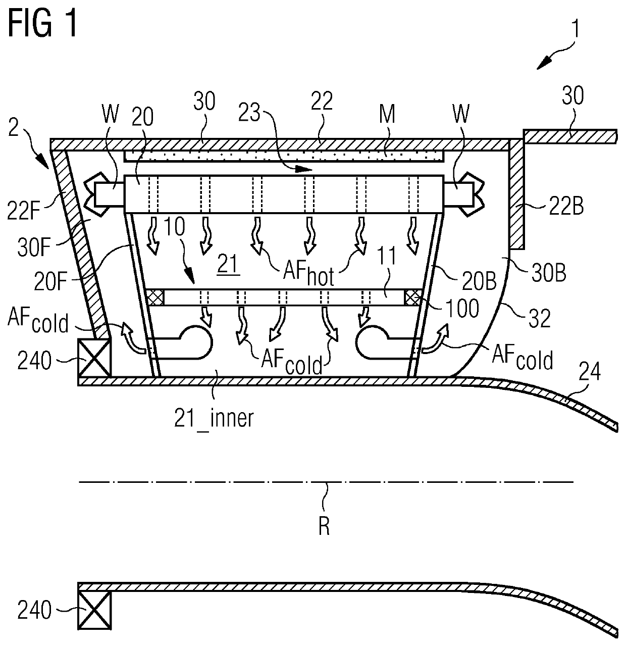
[0030]FIG. 1 shows a generator 2 installed in a wind turbine. The generator 2 is a direct-drive generator 2 with an outer rotor 22 arranged to enclose an inner stator 20. The rotor 22 is supported by a rotor front plate 22F and a main bearing 240. A canopy 30 protects the generator 2 and other components from the exterior environment. A labyrinth seal between the stationary canopy 30 and a rotating brake disc 22B can keep moisture and air-borne particles outside.

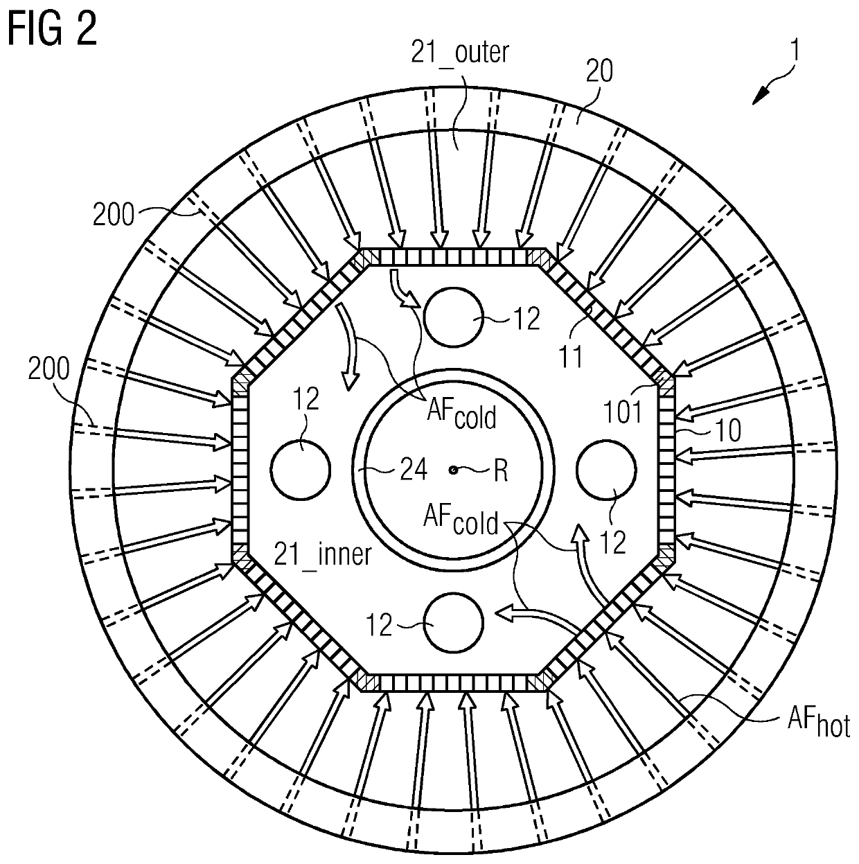
[0031]Magnets M of the rotor 22 face windings W of the stator 20 across a narrow air-gap 23. End plates 20F, 20B mount the stator 20 about a main shaft 24. For clarity, the diagram only shows the upper half of the generator 2, which is installed to rotate about an axis R. An interior cavity 21 is bounded by the stator end plates 20F, 20B, the inside surface of the stator 20, and the main shaft 24. The cooling arrangement 1 uses a partition 10 to separate the stator interior cavity 21 into an outer annular region 21_outer and...


PUM


Abstract

Provided a cooling arrangement for a generator including a stationary armature with an interior cavity bounded by an armature front plate, an armature back plate and a main shaft, which cooling arrangement includes a partition arranged to separate the interior cavity into an outer annular region adjacent to the armature and an inner annular region surrounding the main shaft, and wherein the partition includes a number of heat exchanger units; and a fan assembly arranged in the interior cavity to force hot air from the outer annular region through the heat exchanger units of the partition into the inner annular region and to expel cooled air from the inner annular region of the interior cavity. A wind turbine including such a cooling arrangement for cooling a generator and a method of cooling a generator is also provided.

Description

CROSS-REFERENCE TO RELATED APPLICATIONS[0001]This application claims priority to PCT Application No. PCT / EP2018 / 050526, having a filing date of Jan. 10, 2018, which is based on German Application No. 10 2017 201 641.8, having a filing date of Feb. 2, 2017, the entire contents both of which are hereby incorporated by reference.FIELD OF TECHNOLOGY[0002]The following describes a cooling arrangement for a generator; a wind turbine; and a method of cooling a generator.BACKGROUND[0003]A generator can comprise a stationary armature and a rotating field, or vice versa. An armature may be arranged within the field, or vice versa. In a generator such as a permanent magnet synchronous generator, the field—which carries the magnets is usually the rotor, and the armature—which carries the windings—is usually the stator. A wind turbine comprising such a generator may be realized as a direct-drive wind turbine, for which the rotating hub is mounted directly to the outer rotor. A number of rotor bl...

Claims


Application Information

Patent Timeline
Patent Type & Authority Patents(United States)
IPC IPC(8): H02K7/18H02K9/06F03D80/60F03D9/25
CPCF03D80/60F03D9/25H02K7/1838H02K9/06H02K21/22H02K9/04Y02E10/72H02K9/227
Inventor AIROLDI, GIOVANNI
Owner SIEMENS GAMESA RENEWABLE ENERGY AS
Why Eureka
Try Eureka