
Refrigerant filling apparatus of refrigerating and air conditioning apparatus and refrigerant filling method of refrigerating and air conditioning apparatus

a technology of refrigerant filling which is applied in the direction of lighting and heating apparatus, instruments, packaged goods types, etc., can solve the problems of limited usable range of refrigerating and air conditioning apparatus, difficult to accurately adjust the refrigerant amount in the prior art, and cost and resources

Active Publication Date: 2009-05-07
MITSUBISHI ELECTRIC CORP
View PDF2 Cites 24 Cited by
  • Summary
  • Abstract
  • Description
  • Claims
  • Application Information

AI Technical Summary

Benefits of technology

[0016]The present invention is directed to a refrigerant filling apparatus and a refrigerant filling method of the refrigerating and air conditioning apparatus, capable of automatically finishing the refrigerant filling after filling the refrigerant to the appropriate amount, without installing any other valve except for a valve installed to the refrigerant cylinder in between the refrigerating and air conditioning apparatus and the refrigerant cylinder needed for filling the refrigerant.

Problems solved by technology

This does not only cause problems in costs and resources, but an usable range of the refrigerating and air conditioning apparatus becomes limited.
Considering the refrigerant in large is accumulated in the liquid pipe, a highly accurate refrigerant amount adjustment is difficult in the prior art.

Method used


Image

  • Refrigerant filling apparatus of refrigerating and air conditioning apparatus and refrigerant filling method of refrigerating and air conditioning apparatus
  • Refrigerant filling apparatus of refrigerating and air conditioning apparatus and refrigerant filling method of refrigerating and air conditioning apparatus
  • Refrigerant filling apparatus of refrigerating and air conditioning apparatus and refrigerant filling method of refrigerating and air conditioning apparatus

Examples


first exemplary embodiment

[0035]An air conditioner is described herein as one example of the refrigerating and air conditioning apparatus. Another example of the refrigerating and air conditioning apparatus, besides the air conditioner, is a cooler showcase.

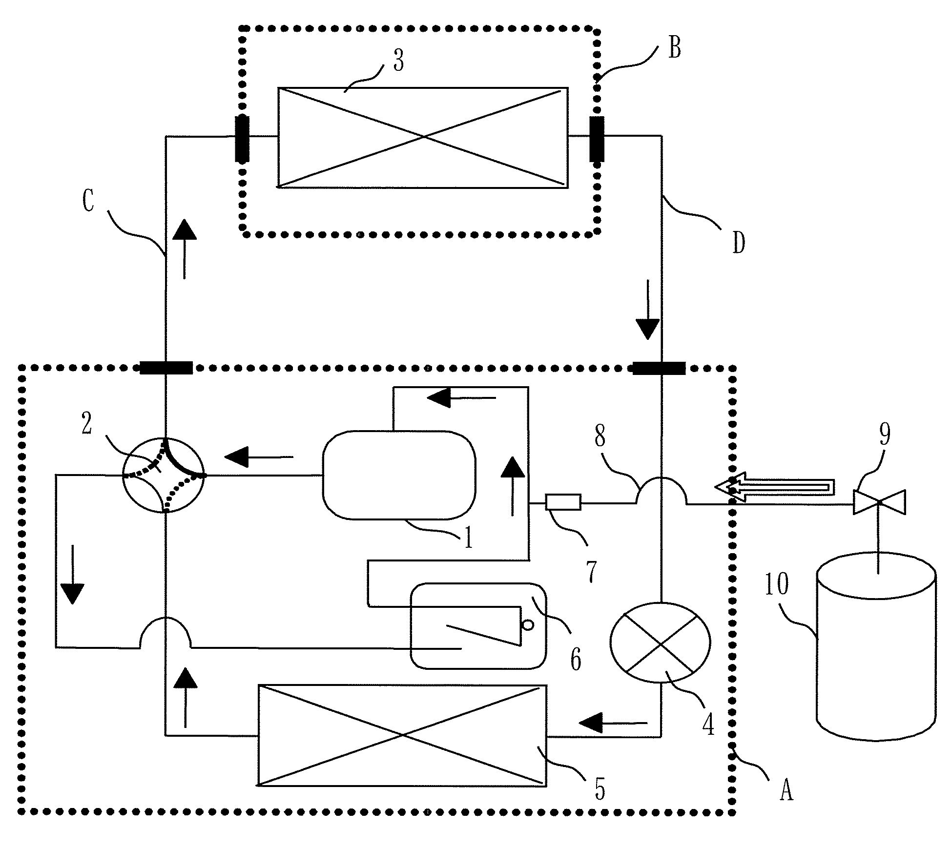
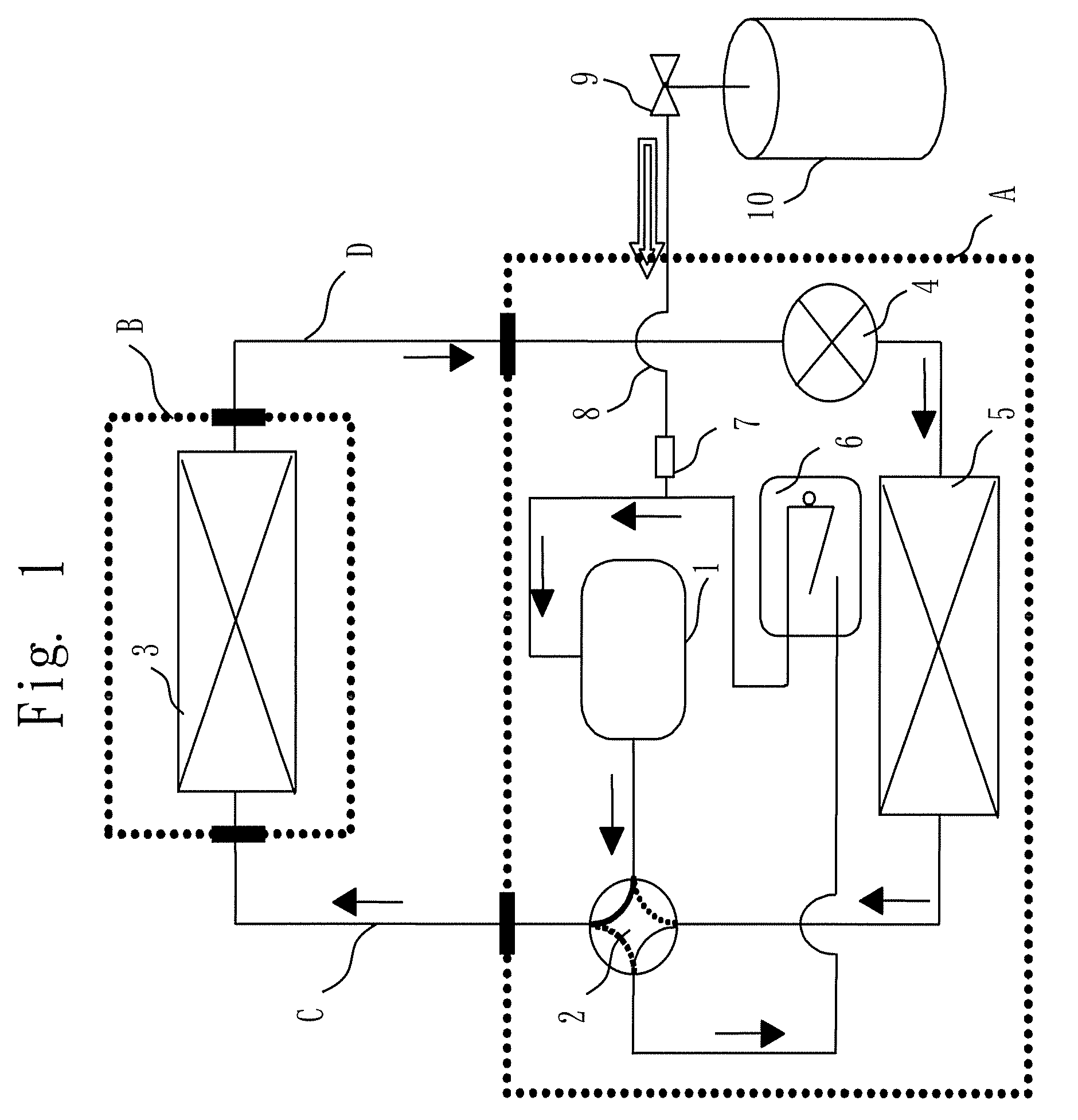
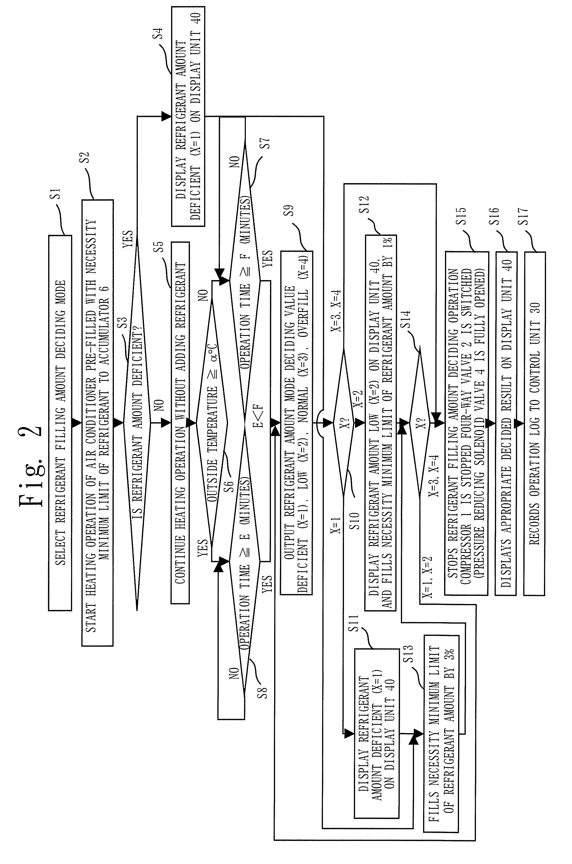
[0036]FIGS. 1 to 8 illustrate the first exemplary embodiment. FIG. 1 illustrates a refrigeration circuit at a time of refrigerant filling of the air conditioner. FIG. 2 illustrates a refrigerant filling flowchart showing a refrigerant filling method. FIG. 3 illustrates an object to be controlled by a control unit 30 when a refrigerant filling amount deciding operation mode has been selected. FIG. 4 illustrates a relation of outside temperature and refrigeration cycle stabilization time. FIG. 5 illustrates a control method of rotation number of the compressor 1 at the time of refrigerant filling. FIG. 6 illustrates a control method of the four-way valve 2 at the time of refrigerant filling. FIG. 7 illustrates a refrigeration cycle during refrigerant fillin...

second exemplary embodiment

[0099]FIG. 9 shows a refrigerant circuit at the time of refrigerant filling of the air conditioner, in accordance with the second exemplary embodiment. Unlike FIG. 1, the pressure reducing solenoid valve 4 is installed to the indoor unit B side.

[0100]When the pressure reducing solenoid valve 4 is installed to the indoor unit B, the refrigerant circuit is looped in a direction of the arrows of FIG. 9, which is similar in contents as the refrigerant filling method of the first exemplary embodiment. That is, to acquire the refrigerant amount mode, if the pressure reducing solenoid valve 4 is located at the outdoor unit A side, this is an indication that the heating operation is required. However, if it is located at the indoor unit B side, this is an indication that the cooling operation is required.

[0101]A section in the refrigerant circuit which requires the refrigerant amount at most, in other words, a density of the refrigerant is the highest, is a path from the condenser (the outd...

third exemplary embodiment

[0102]On the other hand, a refrigerant filling method shown in FIG. 10 having an automatic control valve 15 in between the refrigerant cylinder 10 and the refrigerant circuit, and having a similar refrigerant circuit as FIG. 1, the operation methods described previously are usable.

[0103]FIG. 10 illustrates a refrigerant circuit at the time of refrigerant filling of the air conditioner, in accordance with the third exemplary embodiment.

[0104]According to the refrigerant filling method of the present invention, at a stage of determining the refrigerant amount “normal”, the heating operation mode is stopped, the compressor 1 is stopped at the same time as switching the four-way valve 2, and then, the pressure reducing solenoid valve 4 is fully opened. In this way, a pressure difference in the refrigerant circuit that arises from the heating operation is removed. In consequence of these, an excessive refrigerant filling hereafter is controlled.

[0105]In contrast to this, the circuit show...


PUM

PropertyMeasurementUnit
Fractionaaaaaaaaaa
Temperatureaaaaaaaaaa
Timeaaaaaaaaaa

Abstract

The present invention is directed to a refrigerant filling apparatus of the refrigerating and air conditioning apparatus that can automatically finish filling of a refrigerant after filling to an appropriate amount, without a need to install an extra valve except for a valve provided at a refrigerant cylinder, in between the refrigerating and air conditioning apparatus and the refrigerant cylinder, which is necessary for filling the refrigerant. The refrigerant filling apparatus of the refrigerating and air conditioning apparatus, which includes: a refrigerant circuit having a compressor 1, a four-way valve 2, an indoor side heat exchanger 3, a pressure reducing solenoid valve 4, an outdoor side heat exchanger 3, and an accumulator 6; a refrigerant cylinder 10 connected to the refrigerant circuit; a control unit that controls filling of the refrigerant from the refrigerant cylinder 10 to the refrigerant circuit and decides refrigerant filling modes; and a display unit installed to the control unit and displays the refrigerant filling modes.

Description

BACKGROUND OF THE INVENTION[0001]1. Field of the Invention[0002]The present invention relates to a refrigerant filling apparatus of the refrigerating and air conditioning apparatus and a refrigerant filling method of the refrigerating and air conditioning apparatus.[0003]2. Description of the Related Art[0004]In general, the refrigerating and air conditioning apparatus configuring a refrigeration cycle comprises an indoor unit, an outdoor unit, and connection pipes connecting the indoor unit to the outdoor unit. The indoor unit includes an indoor side heat exchanger. The outdoor unit includes an outdoor side heat exchanger, a compressor, and a pressure reducing solenoid valve. These are connected to the connection pipes at an inside of the outdoor unit. The indoor unit and the outdoor unit configured accordingly are connected by the connection pipes at an installation site to function as the refrigerating and air conditioning apparatus.[0005]There are various environments for instal...

Claims


Application Information

Patent Timeline
IPC IPC(8): B65B3/04F25B39/04G05D23/00
CPCF25B45/00F25B2313/02741F25B2345/001
Inventor SAKAI, TATSUNORIYOSOMIYA, MASATOSHIBA, HIROKUNI
Owner MITSUBISHI ELECTRIC CORP
Learn More