Selective Warming and Heat Isolation For On Board High Pressure Storage Tanks Installed on Gas Fueled Vehicles

a technology for gas fueled vehicles and storage tanks, applied in the direction of container/bottle construction, rigid containers, packaging goods, etc., can solve the problems of affecting the operation and integrity of valves and regulators, causing internal or external leakage, etc., to reduce the risk of fuel gas leakage, reduce the risk of temperature variance, and warm the gas inside the tank

Active Publication Date: 2009-05-07
HONDA MOTOR CO LTD
View PDF23 Cites 11 Cited by
  • Summary
  • Abstract
  • Description
  • Claims
  • Application Information

AI Technical Summary

Benefits of technology

[0003]It is an object of the present invention to provide a thermal management system for warming the gas flow from a high pressure tank and the gas flow control system associated with a gas outlet from the tank. It is a further object to accommodate the effects of thermal cooling and mechanical stress associated with temperature decreases occurring in the tank and the flow control systems because of the ambient environment of the tank or because of temperature changes in the tank assembly resulting from depletion of gas (i.e., gas or tank part cooling caused by pressure reduction or gas expansion in the tank). It is a further object of the invention to eliminate thermally induced leaks in the gas flow fuel systems that result when temperature fluctuations are not stabilized.SUMMARY OF THE INVENTION
[0005]The purpose of the invention is to purposefully warm the areas of the tank proximate the valve and port systems, and thereby to warm the gas itself and to moderate temperature differences to eliminate temperature variances that produce adverse effects in the entire gas flow system. The fuel gas which is exhausted from the tank may be warmed before gas flow enters the tank control valves. The invention provides devices for an internal heat management system wherein gas warming is provided for the tank depletion stage of gas usage. The invention is suitable for use with a tank having an end cap or port at both ends as well as a tank having a single center port layout. The thermal warming system may be integrated with a valve control system for regulating the flow of gas from the tank. The invention warms gas flow inside the tank during driving and reduces the risk of a fuel gas leak in cold climate driving conditions.
[0006]As a result, long term tank durability is increased because the internal temperature differences of the stored gas and the tank components are reduced and the temperature range of the vehicle operation is increased. In examples, valves, seals or a port located around the tank nut or boss are warmed up selectively. Because of the differences in heat mass between the gas per se and the metal valves, seals and port components, selective heating is more effective than warming up whole tank In a variation, the metal valves, seals and port components, are thermally isolated from the gas tank itself. In a further example, the fuel gas which exits from the tank is warmed before the gas enters the metal valve and port / boss components.
[0007]In a representative example, the heat mass of hydrogen stored in a tank is calculated as HeatMassTANK=mHydrogen×Cp=14.7 kJ / K where mHydrogen=1 kg and CpHydrogen=14.7 kj / kg / K. Heat mass of metal components of the tank port system is calculated as HeatMassSUS=mSUS×Cp=0.5 kJ / K where mSUS=3 kg and CpSUS=1.5 kJ / kg / K. In this example, the heat mass of the hydrogen is approximately ten times that of the metal port assembly, namely 14.7 kJ / K÷1.5 kJ / kg / K Thus, in the invention, temperature variances are moderated by selective warming. An efficient warming system for gas flow is provided wherein valves, seals and ports are warmed selectively. The fuel gas exhausted from the tank may be warmed before or while gas flow enters the tank control valves. With a warming device of the invention installed at a control point for gas flow thermal stress is reduced and greater efficiency and lower cost is achieved when compared with systems that heat in bulk the entire quantity of gas stored in the tank interior for the same purpose.

Problems solved by technology

When fuel gas flows from the high pressure tank, the gas loses compression and cools down the valves from inside the tank; the cooling effect of the cold gas flow may interfere with valve and regulator operation and integrity.
Additionally, cold temperature, by itself, may induce internal or external leaks.

Method used


Image

  • Selective Warming and Heat Isolation For On Board High Pressure Storage Tanks Installed on Gas Fueled Vehicles
  • Selective Warming and Heat Isolation For On Board High Pressure Storage Tanks Installed on Gas Fueled Vehicles
  • Selective Warming and Heat Isolation For On Board High Pressure Storage Tanks Installed on Gas Fueled Vehicles

Examples


Embodiment Construction

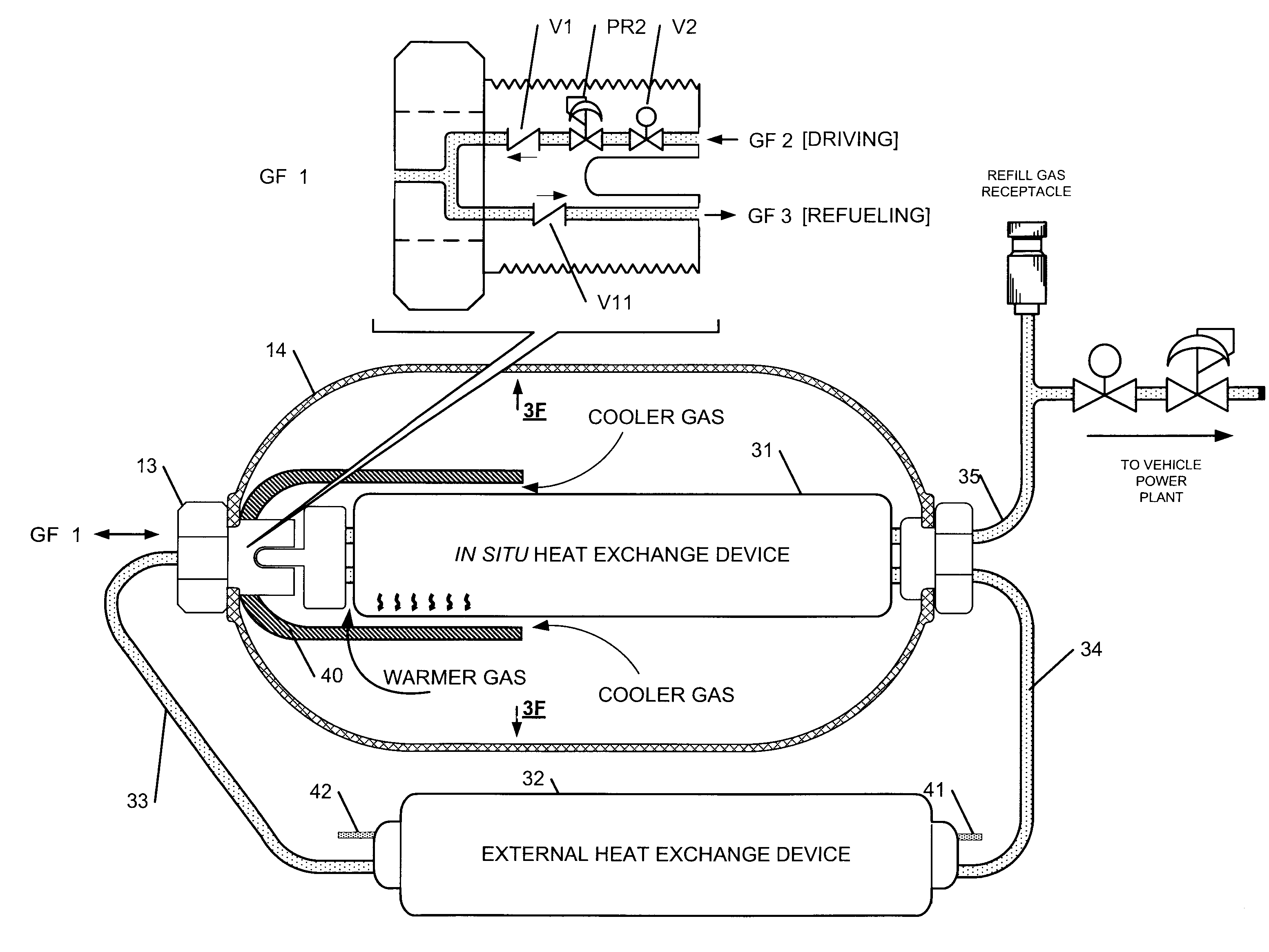
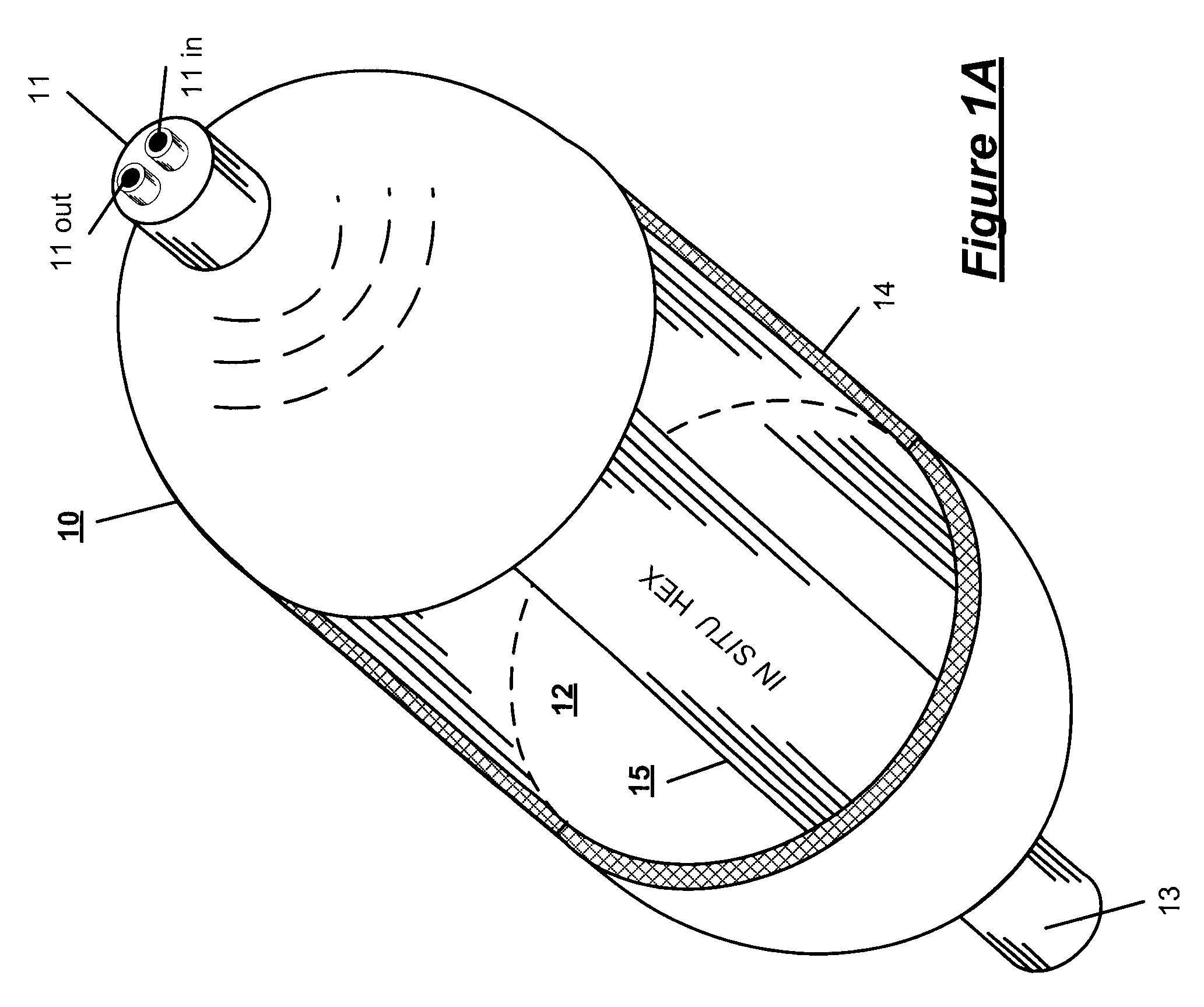
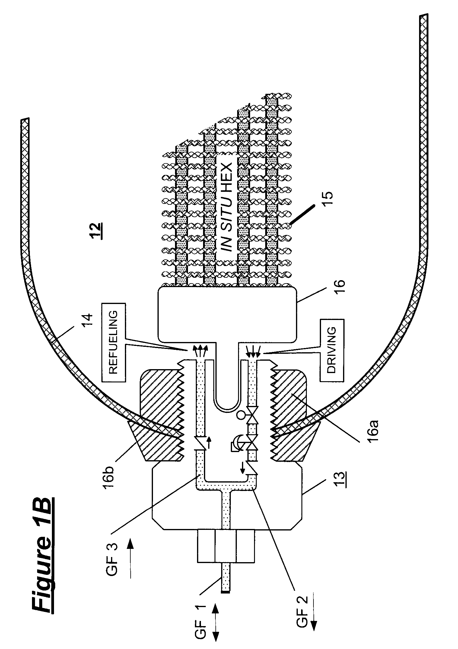
[0022]The invention provides a selective warming system for the thermal management of gas flow from a high pressure vehicle tank. A heat source is disposed proximate to and aligned concentrically with a gas flow control system of the vehicle tank (typically at the tank boss) wherein, depending upon the operating condition of the vehicle or the ambient environment in which the vehicle is operated, the metal heat mass of the gas flow system may be warmed. Preferably, the heat source is disposed in direct contact with the gas flow control system or may be interconnected thereto by a heat pipe. In one embodiment, a heat isolation device surrounds an internal HEX, or the internally installed flow control system at a tank boss. The system of the invention warms the gas flow control system of the tank to a temperature corresponding to at least the minimum lower limit temperature permitted by the temperature tolerance range of the gas flow control system and the tank itself. In the inventio...


PUM

PropertyMeasurementUnit
temperatureaaaaaaaaaa
pressureaaaaaaaaaa

Abstract

A thermal management system for gas flow from an on board high pressure vehicle gas storage tank comprising an on board heat source operatively interconnected with a heater disposed in proximity to the metal component gas outlet flow control system of the on board tank; a thermostat regulating the flow of heat to the heater such that the thermostat regulates the temperature of the metal component outlet flow control system of the tank to a temperature corresponding to at least the minimum lower limit temperature permitted by the temperature tolerance range of metal component outlet flow control system of the tank; and an optional insulating shroud circumferentially disposed surrounding the gas flow heater installed in the system.

Description

FIELD OF THE INVENTION[0001]The present invention relates to a selective warming thermal management system for enhancing the performance of high pressure storage tanks for hydrogen and CNG gas fuel, or other industrial gas, by compensating for thermal and mechanical stresses caused during the depletion of gas from the tanks and by the environmental exposure of the tanks to a low temperature ambient environment. The in situ techniques I have developed and describe in the related applications mentioned above manage the thermal effects of gas flow in a high pressure vehicle storage tank. The present invention adapts gas flow temperature in view of the ambient temperature environment of the storage tank and the thermal cooling of the gas that is caused by depletion of the high pressure gas from within the tank as the fuel is consumed by the vehicle engine and the tank empties. Stresses caused by the thermal conditions of the tank environment and changes associated with the depletion of ...

Claims


Application Information

Patent Timeline
Patent Type & Authority Applications(United States)
IPC IPC(8): B60H1/00F17C1/00
CPCF17C5/06F17C2201/0104F17C2205/00F17C2205/0323Y02E60/321F17C2223/036F17C2250/0439F17C2265/066F17C2205/0397Y10T137/6525Y02E60/32
Inventor HANDA, KIYOSHI
Owner HONDA MOTOR CO LTD
Why Eureka
Try Eureka