Modular heat exchange system

Active Publication Date: 2009-05-07
WILLEMS RONY
View PDF26 Cites 63 Cited by
  • Summary
  • Abstract
  • Description
  • Claims
  • Application Information

AI Technical Summary

Benefits of technology

[0010]It is an aim of the present invention to provide a modular heat exchange

Problems solved by technology

These known heating/cooling systems have the di

Method used


Image

  • Modular heat exchange system
  • Modular heat exchange system
  • Modular heat exchange system

Examples


first embodiment

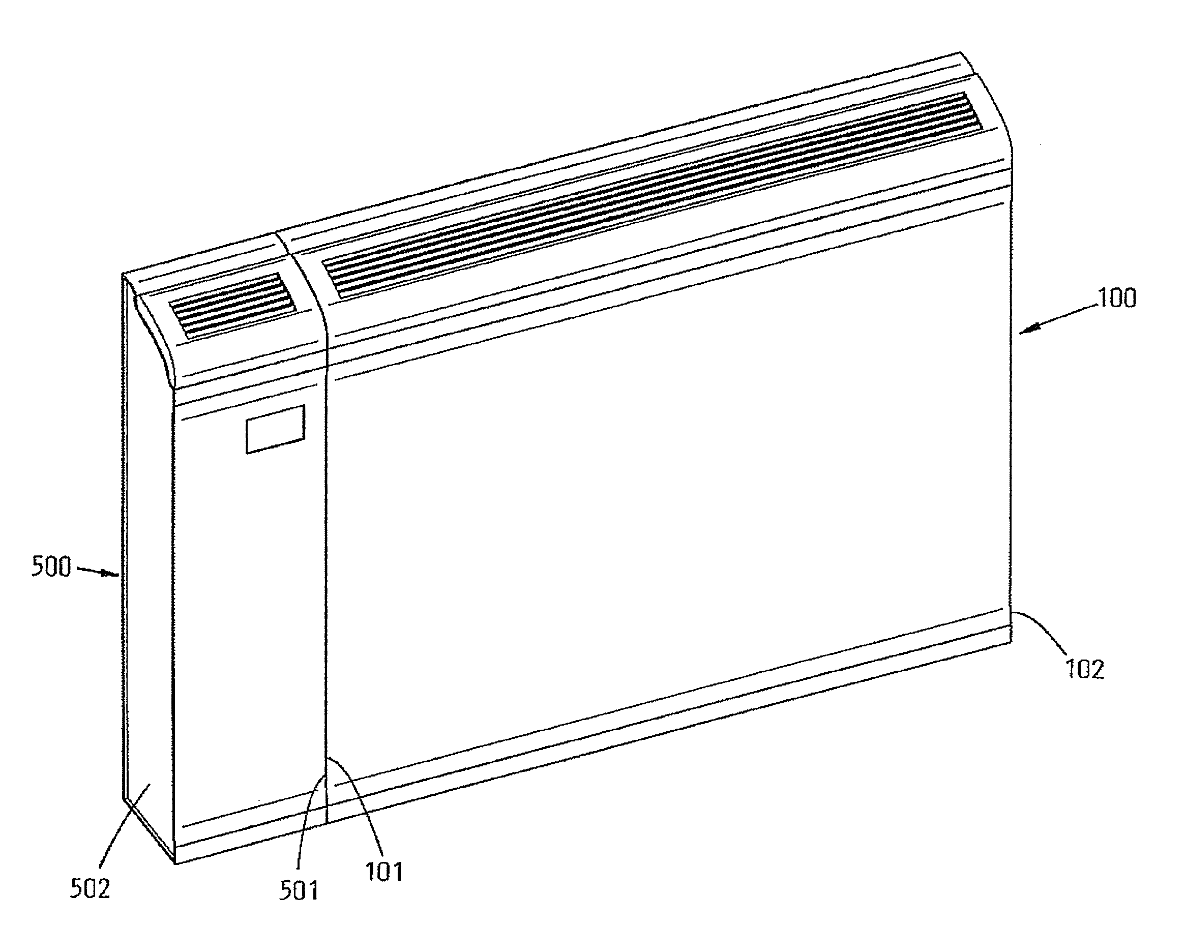
[0092]FIG. 1 shows a modular heat exchange system according to the invention. The system comprises one basic heat exchange element 100 and one non-heat-exchange add-on element 500, more particularly a control unit for controlling the heat exchange element. The heat exchange element 100 has a predetermined rectangular shape with opposite lateral sides 101, 102. The control unit 500 has a predetermined rectangular shape which nicely fits with that of the heat exchange element 100. To this end the control unit has lateral sides 501, 502 which are complementary to the opposite lateral sides 101, 102 of the heat exchange element 100. As a result, when the heat exchange element and the add-on element are fixed adjacent to each other with the complementary sides facing each other as shown in FIG. 1, the rectangular shape of the heat exchange element 100 continues into the rectangular shape of the control unit 500, so that the whole looks like a single unit. In the figure the control unit 5...

second embodiment

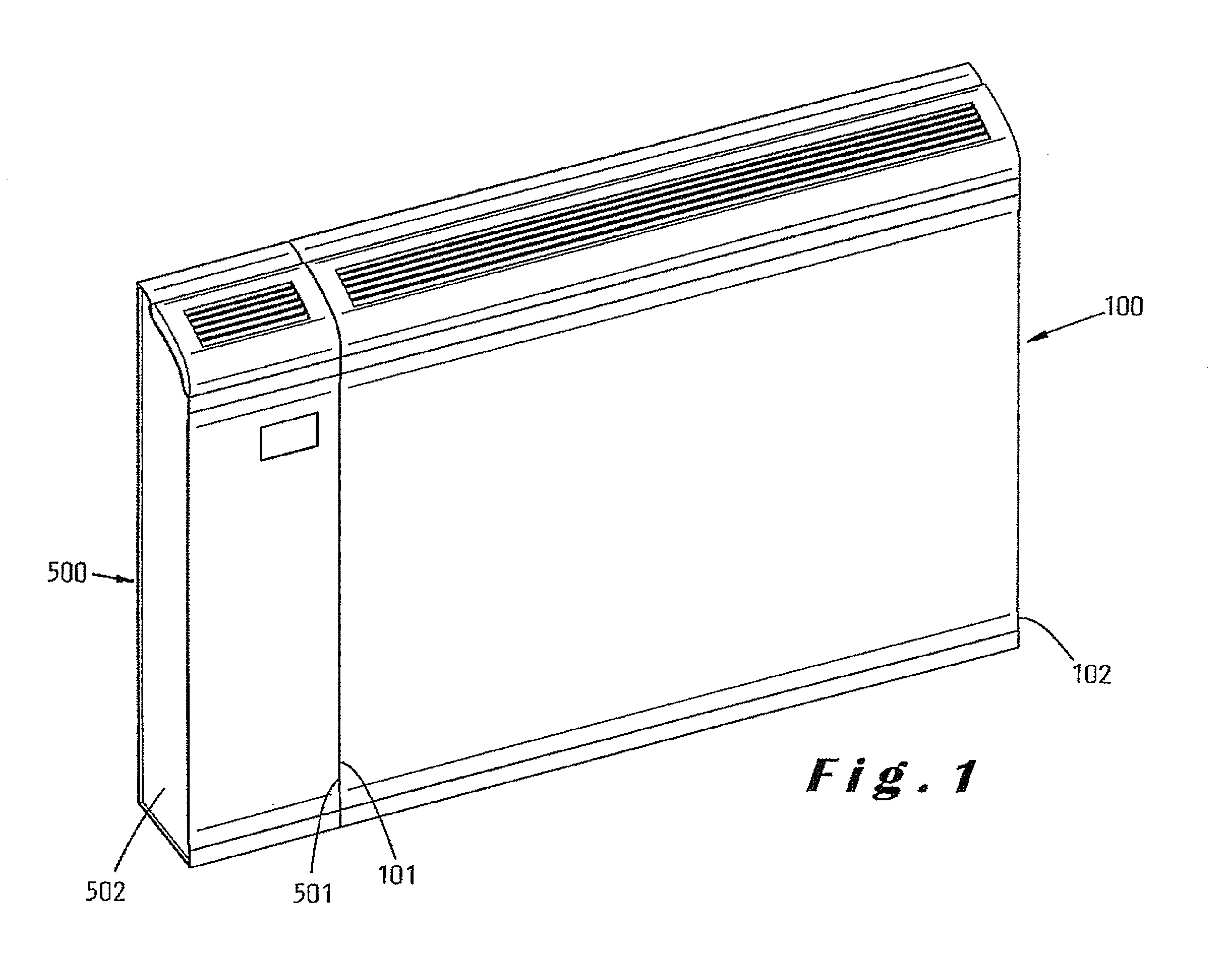
[0093]FIG. 2 shows a modular heat exchange system according to the invention. The system comprises one heat exchange element 100, the same one as in FIG. 1, and one non-heat-exchange add-on element 520, more particularly a light unit. The light unit 520 has two lateral sides 521, 522 which are complementary to those of the heat exchange element 100.

third embodiment

[0094]FIG. 3 shows a modular heat exchange system according to the invention. The system comprises two heat exchange elements 100, the same ones as in FIG. 1, and a corner element 540 as non-heat-exchange add-on element. This corner element 540 has sides 541, 542, complementary to the sides 101, 102 of the heat exchange elements 100, which makes it possible to mount the two heat exchange elements 100 in an angular configuration in the corner of a room. The top side of the corner element 540 is removable for enabling cleaning of the space in the corner.


PUM


Abstract

A modular heat exchange system for use in a central heat exchange installation in buildings, including at least one heat exchange element equipped for exchanging heat between environmental air and a fluid which is conducted through the heat exchange element. The heat exchange element has a predetermined first shape with opposite lateral sides. At least one non-heat-exchange add-on element, equipped for adding a given additional functionality to the system, has a predetermined second shape with a complementary lateral side to one of the opposite lateral sides of the heat exchange element.

Description

TECHNICAL FIELD[0001]The present invention relates to modular heat exchange systems for use in central heat exchange installations in buildings.BACKGROUND ART[0002]From EP 1 684 045 A2 a building heating system is known which is 10 composed of a plurality of plastic modular heat exchange elements. Each of the modular elements is composed of two horizontal sleeves and vertical ducts or branches, the ends of which are connected to the sleeves so as to enable the passage of heat exchange fluid, which enters from one of these sleeves, flows through the ducts or branches and exits from the other sleeve. Several modular elements are joined together to form a radiator by axially coupling the horizontal sleeves.[0003]From EP 0 524 085 A1 a radiator is known which is made up of identical or similar heating elements, through which a heating fluid circulates, and making it possible to adapt its outer dimensions by juxtaposition of the heating elements. In accordance with the invention, each he...

Claims


Application Information

Patent Timeline
IPC IPC(8): F25B29/00F24F3/044
CPCF24D19/0082F24D19/0087F24D19/02F28F3/048F24D19/1009F28D1/0308F24D19/06Y02B30/00
Inventor STROOBANTS, MARCEL
Owner WILLEMS RONY
Why Eureka
Try Eureka