Split Return Wing

a return wing and wing technology, applied in the field of plane wing splits, can solve the problems of large air resistance of the whole wing, great unbalanced moment, aircraft losing balance, etc., and achieve the effect of ensuring horizontal stability, ensuring direct stability, and maximum lift for

Inactive Publication Date: 2009-05-07
MU QIAN
View PDF9 Cites 4 Cited by
  • Summary
  • Abstract
  • Description
  • Claims
  • Application Information

AI Technical Summary

Benefits of technology

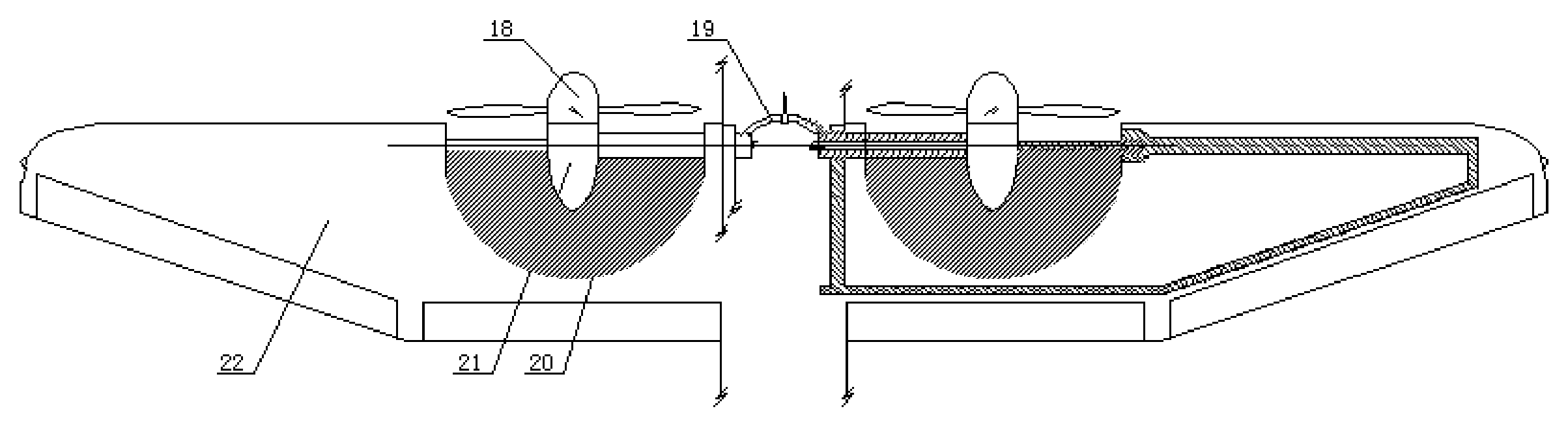
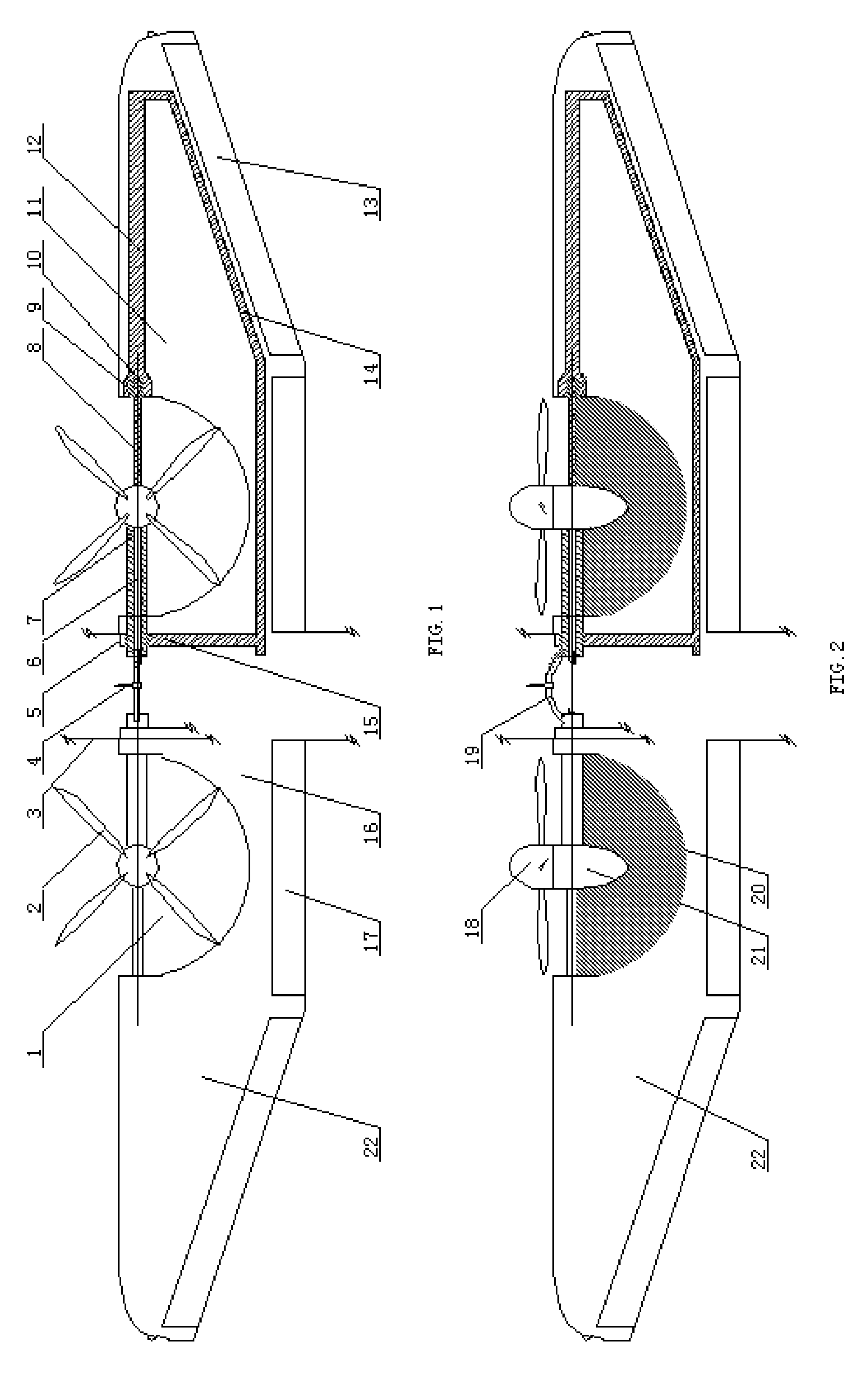
[0008]The positive effects of the present invention are: the wing has the split return sector wing-pieces, and the split return sector wing-pieces could tilt with the tilting-able dynamic devices. The split return sector wing-pieces split downward from the main wing body when the aircraft is taking off & landing vertically, so that the axes of the tilting-able dynamic devices are all perpendicular to the earth. In this case, the aircraft could obtain the lift force, that realize the aircraft taking off & landing vertically, hovering in the air, flying forward, flying backward and so on. At this time, the whole wing, especially the big wingspan outer-wings still keep horizontally; when the aircraft begins to fly horizontally, the split return sector wing-pieces tilt upward with the tilting-able dynamic devices, so they return to the main wing body again to form the complete wing, then the tilting-able dynamic devices could jet backward that they become thrusters completely. So, the tilting-able dynamic devices thrust the aircraft flying horizontally in high speed, that it could solute the existing technical problems.
[0009]The present invention has the following unique and outstanding advantages: 1. The left tilting-able dynamic device and the right tilting-able dynamic device are set both sides of the aircraft's axis as close as possible, that it ensures their outer atmosphere field are same. The unbalance-disturbed moment is eliminated, it ensures the horizontal stability when the aircraft is taking off & landing vertically, it also ensures the direct stability when the aircraft flies horizontally in high speed; 2. The split return sector wing-pieces split downward from the main wing body when the aircraft is taking off & landing vertically, which ensures that the tilting-able dynamic devices could jet downward completely, so the aircraft could obtain the maximum lift force; 3. The size of wing is not restricted, especially the big wingspan outer-wings, which have the high lift drag ratio, are fundamental guarantee for stability, safety, economy and other important flying qualities of the aircraft; 4. The dynamic jet flow of the tilting-able dynamic devices have small effect on the flow field of wing, the whole wing, especially the big wingspan outer-wings still keep horizontally in the smooth laminar flow from beginning to end, so, the aircraft could obtain very stable lift force, it is extraordinarily important for the aircraft flying transitionally; 5. Compare to the aircraft, which tilts the whole wing, the split return sector wing-pieces let the air-resistance area decrease to minimum. The split return sector wing-pieces are also in the high-speed jet flow of the tilting-able dynamic devices, so that the speed of jet flow on their surface is far greater than the air-resistance flow. The highest speed of transitional flying is about 120 kilometers / hour, so the air-resistance can be neglected; 6. The active line of the lift force is just through the aircraft's center of gravity. The aircraft's center of gravity, the center of the wing's aerodynamic force and the focus of the aircraft can be the best match. So, the aircraft could get overall balance; 7. The speed of jet flow is very high, at the same time the bottom jet flow could be isolated by the main wing, so they hardly flow above the edge of the propeller plate again, in this case, dangerous vortex ring never turn up; 8. The power transmission path is short, structure is simple, weight is light, and the transmission efficiency is high. The structure of the split return sector wing-pieces could be match two flight states mostly: which are the aircraft taking off & landing vertically and flying horizontally in high speed. The big wingspan, which has high lift drag ratio, is the foundation stone of the aircraft flying in subsonic speed.

Problems solved by technology

Propellers, or contra-rotating propellers or ducted fans are usually installed on the ends of wing, or tilted with the whole wing as to form tilting-able dynamic force for aircraft, that unbalanced moment is great when the aircrafts are taking off & landing vertically.
In this case, the aircrafts will lose the balance to roll athwartships, or the air resistance of the whole wing will be great that the aircrafts hardly fly transitionally.
So, these structures of wing could not satisfy the demand of persons, with which the aircrafts are taking off & landing vertically.

Method used


Image

  • Split Return Wing
  • Split Return Wing

Examples


Embodiment Construction

[0013]The present invention is the split return wing, which contains the main wing body 16, the main wing body 16 connects with the fuselage main support frame 15, the tilting-able segments of main wing-spar are installed on the fuselage main support frame 15 actively. Two ends of the tilting-able segments of main wing-spar connect with the fixed segments of main wing-spar actively. Two split return sector wing-pieces are installed on the right and the left tilting-able segment of main wing-spar separately. There is one group tilting-able dynamic device in front of every split return sector wing-piece. The split return sector wing-pieces can be in the perforation spaces in the main wing body, their shapes are same. And two big wingspan outer-wings are set on the right and left of the main wing body separately. When the aircraft is taking off & landing vertically, two tilting-able dynamic devices are tilted upward by tilting-able segments of main wing-spar, at the same time, the spli...


PUM


Abstract

The present invention concerns a sort of split return wing. The split return wing contains main wing body, which connects with the fuselage main support frame, and the tilting-able segments of main wing-spar are installed on the fuselage main support frame actively. Two ends of the tilting-able segments of main wing-spar connect with the fixed segments of main wing-spar actively. Two split return wing sector wing-pieces are installed on the right and the left tilting-able segment of main wing-spar separately. There is one group tilting-able dynamic device in front of every split return sector wing-piece. The split return sector wing-pieces can be in the perforation spaces of the main wing body, and their shapes are same. And two big wingspan outer-wings are set on the right and left of the main wing body separately. The Split return wing will decrease unbalanced moment of aircraft to the minimum when the aircraft is taking off & landing vertically. They also will decrease the air resistance of the whole wing to the minimum when the aircraft flies transitionally. At the same time, the whole wing, especially the big wingspan outer-wings still keep horizontally from beginning to end. In this case, it will ensure that the aircraft is taking off & landing vertically, and will fly transitionally toward horizontal high-speed flight smoothly, so, the wing could satisfy the demand of persons.

Description

CROSS REFERENCE TO RELATED PATENT APPLICATION[0001]This application claims the priority of the Chinese patent application No. 200720029535.7 with filing date of Nov. 5, 2007, the content of which is incorporated herein by reference thereto.FIELD OF THE INVENTION[0002]The present invention concerns a sort of plane wing, further concerns a split return wing.BACKGROUND OF THE INVENTION[0003]Nowadays, varies aircrafts, which respectively use propellers or contra-rotating propellers or ducted fans, taking off & landing vertically. Propellers, or contra-rotating propellers or ducted fans are usually installed on the ends of wing, or tilted with the whole wing as to form tilting-able dynamic force for aircraft, that unbalanced moment is great when the aircrafts are taking off & landing vertically. In this case, the aircrafts will lose the balance to roll athwartships, or the air resistance of the whole wing will be great that the aircrafts hardly fly transitionally. The above situation is ...

Claims


Application Information

Patent Timeline
Patent Type & Authority Applications(United States)
IPC IPC(8): B64C3/00
CPCB64C29/0033
Inventor MU, QIAN
Owner MU QIAN
Why Eureka
Try Eureka