Organic Electroluminescence Display Device and Manufacturing Method Thereof
a technology of electroluminescence display device and organic electroluminescence, which is applied in the manufacture of tube/lamp screen, luminescent coating application, discharge tube luminescnet screen, etc., can solve the problems of inability to achieve sufficient performance, and inability to meet the requirements of the application. , to achieve the effect of improving the barrier property against moisture, low hydrogen content and high density
- Summary
- Abstract
- Description
- Claims
- Application Information
AI Technical Summary
Benefits of technology
Problems solved by technology
Method used
Image
Examples
embodiment 1
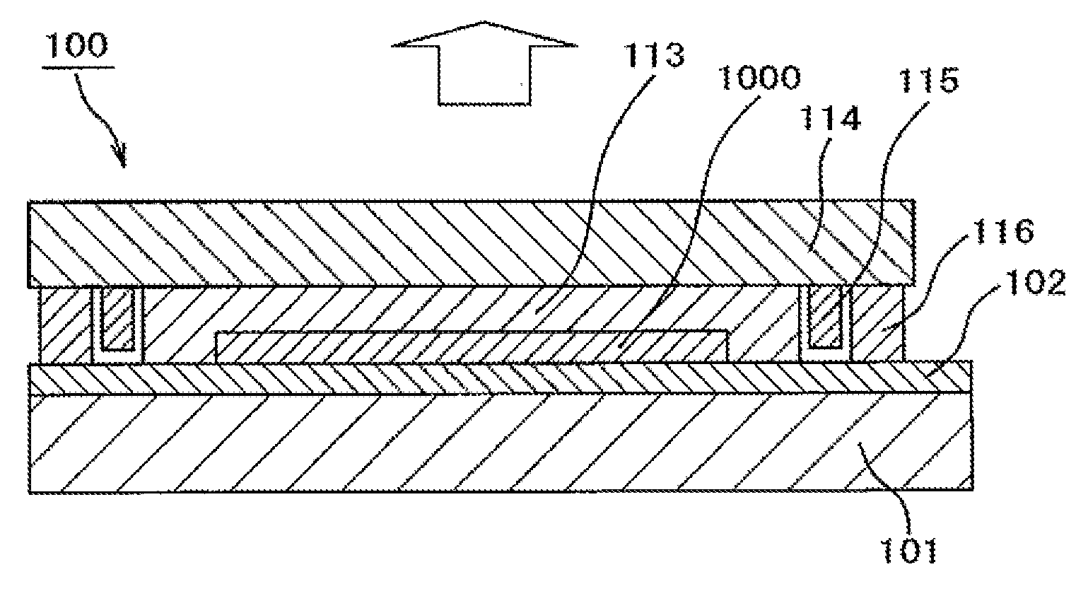
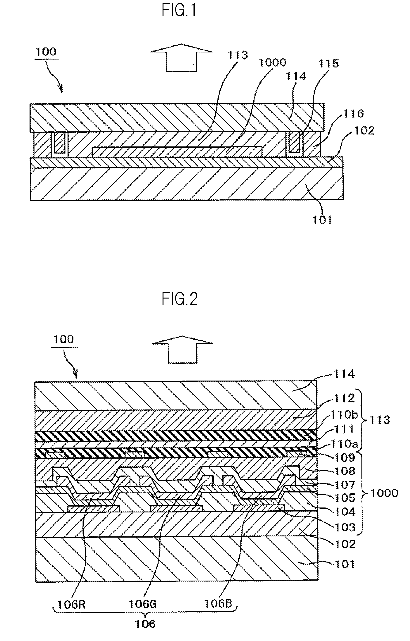
[0073]FIG. 1 is a cross-sectional view illustrating a main portion of an organic EL panel 100. In FIG. 1, the organic EL panel 100 includes: a circuit board 101 including a glass substrate; a circuit formation section 102 such as a thin film transistor (TFT); an organic EL element section 1000 having an organic EL element formed thereon; a protective film 113 formed so as to cover the organic EL element section 1000; a sealing glass 114; a drying agent 115; and a sealing agent 116. The outline arrow indicates a direction of light emission, and in a case of this embodiment, light is to be taken out from the sealing glass 114 side.
[0074]The organic EL element section 1000 is sealed with the sealing glass 114, the protective film 113, the sealing agent 116, and the circuit board 101 including the circuit formation section 102. An organic film made of acrylic, polyimide or the like, or an inorganic insulating film such as an Si oxide film or an Si nitride film is formed as a planarizing...
embodiment 2
[0107]This embodiment provides an example of application of the present invention to a bottom emission type organic EL panel, and is similar to Embodiment 1 except for this point. FIG. 7 is a cross-sectional view illustrating a main portion of an organic EL panel 100. In FIG. 7, the organic EL panel 100 includes: a circuit board 101 such as a glass substrate; a circuit formation section 102 including a thin film transistor (TFT); an organic EL element section 1000 having an organic EL element formed thereon; a protective film 113 formed so as to cover the organic EL element section 1000; a sealing glass 114; a drying agent 115; and a sealing agent 116. The outline arrow indicates a direction of light emission, and in a case of this embodiment, light is to be taken out from the circuit board 101 side. The organic EL element section 1000 is sealed with the sealing glass 114, the protective film 113, the sealing agent 116, and the circuit board 101 including the circuit formation secti...
embodiment 3
[0112]This embodiment provides an example of application of the present invention to an organic EL panel in which hollow sealing is provided, and is similar to Embodiment 1 except for this point. FIG. 9 is a cross-sectional view illustrating a main portion of an organic EL panel 100. In FIG. 9, the organic EL panel 100 includes a circuit board 101 such as a glass substrate; a circuit formation section 102 including a thin film transistor (TFT); an organic EL element section 1000 having an organic EL element formed thereon; a protective film 113 formed so as to cover the organic EL element section 1000; a sealing glass 114; a drying agent 115; and a sealing agent 116.
[0113]In a case of this embodiment, a sealing space 117 is newly formed between the sealing glass 114 and the protective film 113. This embodiment differs in this point from Embodiment 1, and is similar in other points to Embodiment 1. The outlinear row indicates a direction of light emission, and in the case of this emb...
PUM
 Abstract
Description
Claims
Application Information
 - R&D
- Intellectual Property
- Life Sciences
- Materials
- Tech Scout
- Unparalleled Data Quality
- Higher Quality Content
- 60% Fewer Hallucinations
Browse by: Latest US Patents, China's latest patents, Technical Efficacy Thesaurus, Application Domain, Technology Topic, Popular Technical Reports.
© 2025 PatSnap. All rights reserved.Legal|Privacy policy|Modern Slavery Act Transparency Statement|Sitemap|About US| Contact US: help@patsnap.com


