
Circuit for phase locked oscillators

a phase lock and oscillator technology, applied in the direction of gaseous masers, automatic control of pulses, magnetic recording, etc., can solve the problems of difficult to achieve effective phase lock through serial connection, difficult to define the shape-anisotropy field of the magnetic layer in the spin torque oscillator, etc., to achieve the effect of increasing the tolerance for deviating anisotropy fields

Active Publication Date: 2009-05-07
PERSSON JOHAN +2
View PDF1 Cites 49 Cited by
  • Summary
  • Abstract
  • Description
  • Claims
  • Application Information

AI Technical Summary

Benefits of technology

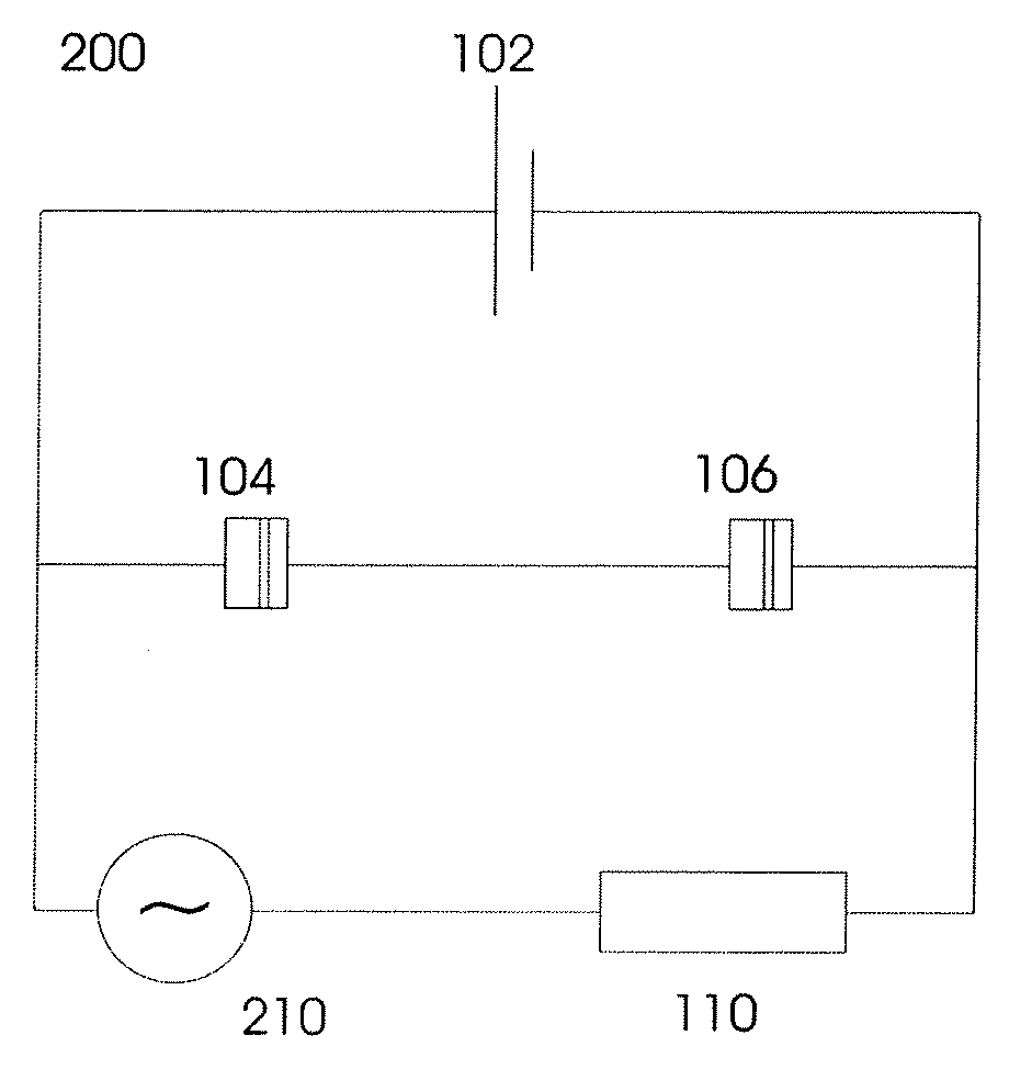
[0021]An advantage of the present invention is that the controlled phase shift significantly increases the tolerance for deviating anisotropy fields, which makes manufacturing of spin torque oscillator devices much more feasible in practice.

Problems solved by technology

However, discrepancies in fabrication mean that the shape-anisotropy fields of magnetic layers in the spin torque oscillators can differ greatly, especially as elements get smaller.
When the size of components reach the nano level, surface roughness becomes an increasing problem, and edge effects automatically introduce a variation in the effective anisotropy field.
This will make an effective phase lock through serial connection hard to achieve.

Method used


Image

  • Circuit for phase locked oscillators
  • Circuit for phase locked oscillators
  • Circuit for phase locked oscillators

Examples


Embodiment Construction

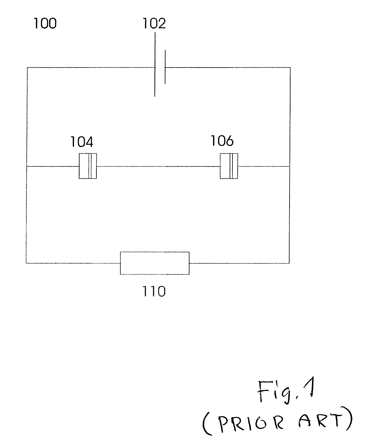
[0034]Referring now to FIG. 1 (PRIOR ART), a circuit 100 according to the prior art is illustrated. The circuit 100 comprises a DC current source 102 and two spin torque oscillators (STO:s) 104, 106 coupled in series. A resistive load 110 is also shown connected in parallel with the STO:s 104, 106. It should be noted that the resistive load 110 is not necessarily a physical resistor, but may be considered as a model of the inherent resistive load in the circuit.

[0035]When a DC current is applied to the STO:s 104, 106, the STO:s 104, 106 will start to oscillate due to the spin torque effect described above, generating an net AC current that is created through their shifting resistances. Under specific circumstances (i.e. for certain intervals of DC current strength) the two STO:s will synchronize their oscillations, resulting in a significantly stronger generated AC current. This AC current is mediated through the resistive load 110.

[0036]The frequency of the generated AC current can...


PUM


Abstract

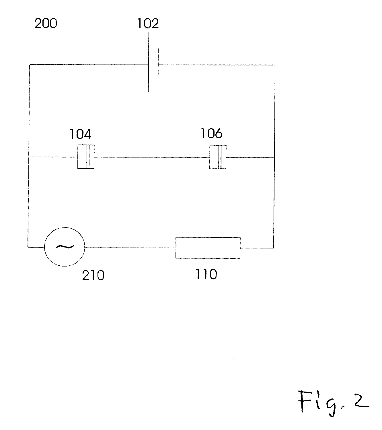
The present invention pertains to a circuit comprising a DC current source and at least two spin torque oscillators, the at least two spin torque oscillators being electrically coupled to each other and to the DC current source. A circuit comprising phase shifting means is connected in such a way as to cause a phase shift between current and voltage through the spin torque oscillators. An advantage of the present invention is that the controlled phase shift significantly increases the tolerance for deviating anisotropy fields, which makes manufacturing of spin torque oscillator devices much more feasible in practice.FIG. 2, wherein the DC current source comprises phase shifting means.

Description

FIELD OF THE INVENTION[0001]The present invention relates generally to phase locked spin torque oscillators, and more particularly to a circuit comprising electrically coupled phase locked spin torque oscillators and use of such a circuit.BACKGROUND OF THE INVENTION[0002]Magnetic tunnel junctions and spin valves are commonly used as MRAM storage bits and magnetic read heads. The discovery that the magnetization of a free layer can be manipulated by means of a transferred spin polarized current, enables the magnetization of the free layer of such a structure to be manipulated in such a way that the magnetization of the layer keeps rotating. The resulting oscillation in resistance of the structure can be utilized for switching of MRAM elements or as an oscillating component, a spin torque oscillator (STO).[0003]A spin valve is typically a sandwiched structure consisting of two ferromagnetic layers separated by a thin non-magnetic spacer layer. A magnetic tunnel junction (MTJ) would ha...

Claims


Application Information

Patent Timeline
Patent Type & Authority Applications(United States)
IPC IPC(8): H03B28/00
CPCY10T428/1107H03B15/006
Inventor PERSSON, JOHANZHOU, YANAKERMAN, JOHAN
Owner PERSSON JOHAN
Learn More