Image providing apparatus, image display apparatus, and image display system constituted by the same

Inactive Publication Date: 2009-05-07
PANASONIC CORP
View PDF19 Cites 5 Cited by
  • Summary
  • Abstract
  • Description
  • Claims
  • Application Information

AI Technical Summary

Benefits of technology

[0018]According to the first aspect, when the providing side infrared reception section is capable of receiving the off data, the supply of power to the providing side wireless communication section may be stopped, whereby it is possible to sufficiently reduce the electricity consumed by the image providing apparatus while power to the image providing apparatus is off.
[0019]According to the second aspect, when the off data has not been received by the providing side infrared reception section, the supply of power to the providing side wireless communication section may not be stopped, whereby it is possible, by the providing side wireless communication section, to transmit/receive data between the image providing apparatus and the image display apparatus when power to the image providing apparatus is off.
[0020]According to the third aspect, in the case where the supply of power to the providing side wireless communication section is not stopped, when, for example, the installation positions of the image providing apparatus and the image display apparatus change and the providing side infrared reception section becomes capable of receiving the off data transmitted from the image display apparatus, the supply of power to the providing side wireless communication section may be stopped, whereby it is possible to sufficiently reduce the electricity consumed by the image providing apparatus.
[0021]According to the fourth aspect, in the case where the supply of power to the providing side wireless communication section is stopped, when, for example, the installation positions of the image providing apparatus and the image display apparatus change and the providing side infrared reception section becomes incapable of receiving data transmitted from the image display apparatus, the supply of power to the p

Problems solved by technology

Here, the problem of an image display system separately including devices such as an image providing apparatus and an image display a

Method used


Image

  • Image providing apparatus, image display apparatus, and image display system constituted by the same
  • Image providing apparatus, image display apparatus, and image display system constituted by the same
  • Image providing apparatus, image display apparatus, and image display system constituted by the same

Examples


first embodiment

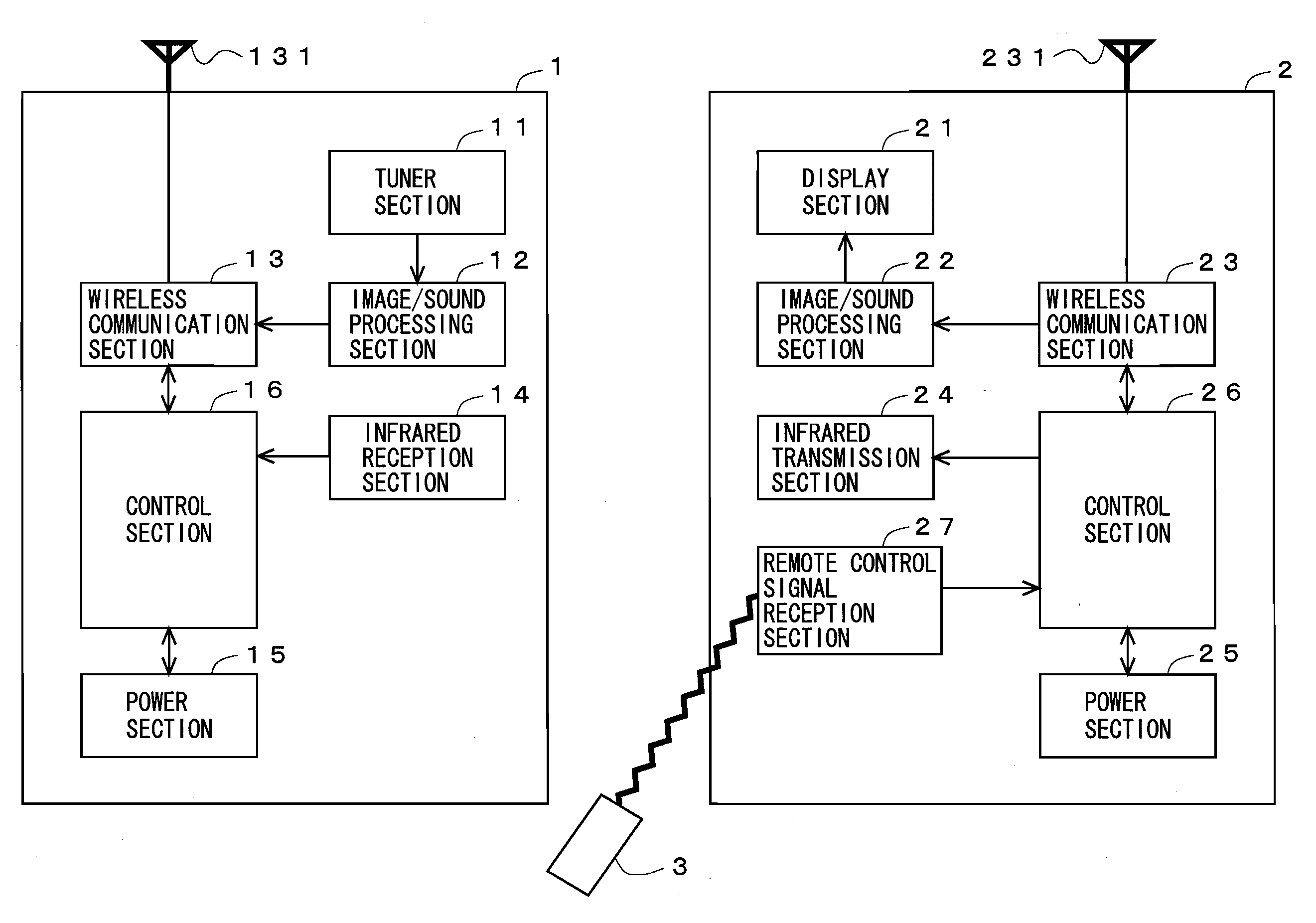
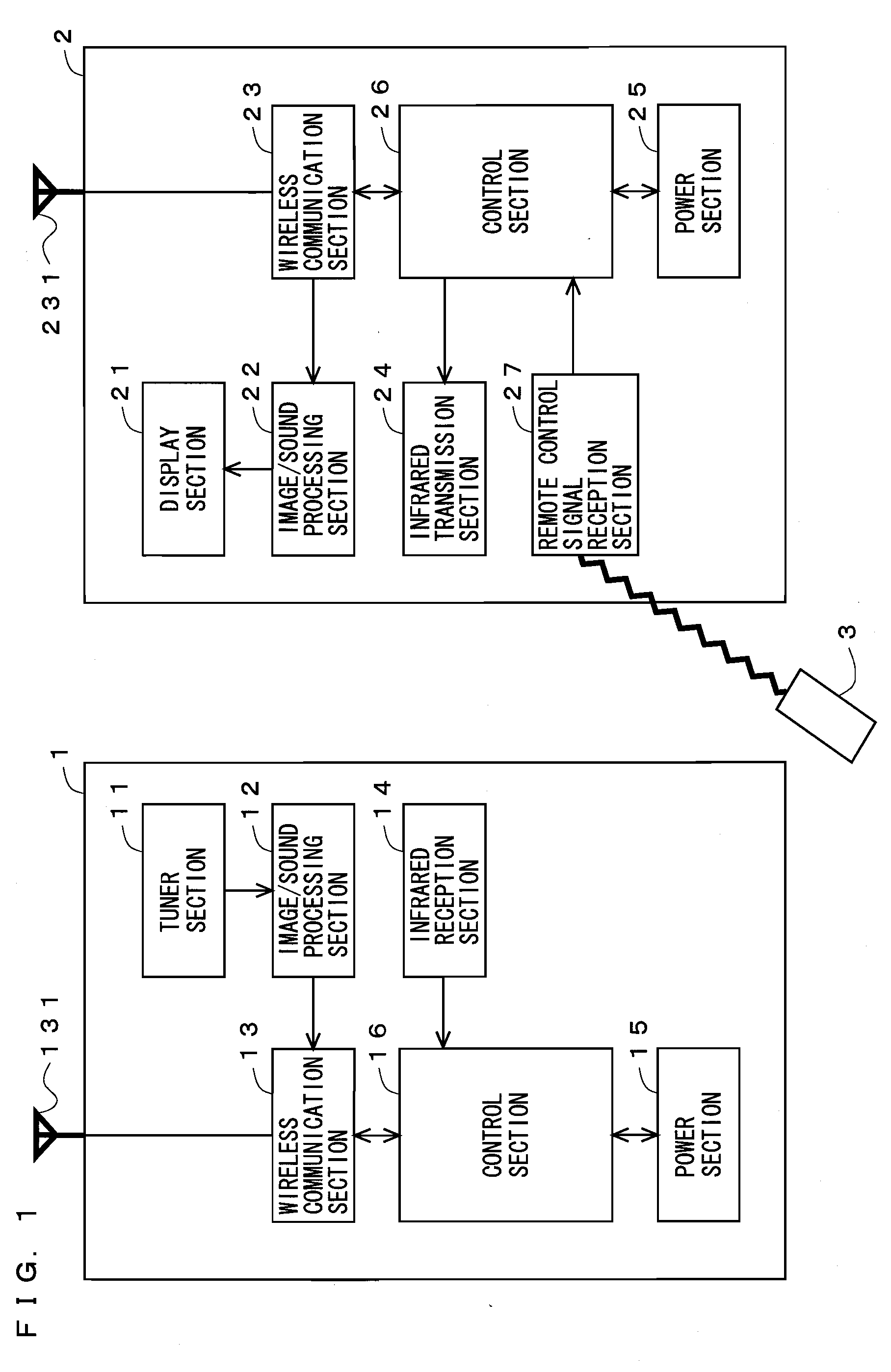
[0050]With reference to FIG. 1, an image display system according to a first embodiment of the present invention will be described. FIG. 1 is a block diagram showing an example structure of the image display system according to the first embodiment. The image display system includes an image providing apparatus 1 and an image display apparatus 2.

[0051]The image providing apparatus 1 includes a tuner section 11, an image / sound processing section 12, a wireless communication section 13, an infrared reception section 14, a power section 15, and a control section 16. The image display apparatus 2 may be, for example, a television receiver. The image display apparatus 2 includes a display section 21, an image / sound processing section 22, a wireless communication section 23, an infrared transmission section 24, a power section 25, a control section 26, and a remote control signal reception section 27.

[0052]First, each element of the image providing apparatus 1 will be described. The tuner...

second embodiment

[0077]Next, an image display system according to a second embodiment of the present invention will be described. Since the image display system according to the present embodiment is similar in structure to the image display system according to the first embodiment shown in FIG. 1, each element according to the present embodiment will not be described in detail.

[0078]Next, prior to describing the process of the image display system according to the present embodiment in detail, the purpose of the process and its overview will be described. In the above-described first embodiment, the description is given on the assumption that the installation positions of the image providing apparatus 1 and the image display apparatus 2 do not change. However, as shown in FIG. 6, there may be a case where the installation positions of the image providing apparatus 1 and the image display apparatus 2 change after power to the image providing apparatus 1 is turned off, and the reception state of the ...

third embodiment

[0087]With reference to FIG. 9, an image display system according to a third embodiment of the present invention will be described. FIG. 9 is a block diagram showing an example structure of the image display system according to the third embodiment of the present invention. The image display system according to the present embodiment includes an image providing apparatus 1 and an image display apparatus 2. The image providing apparatus 1 includes a tuner section 11, an image / sound processing section 12, a wireless communication section 13, an infrared reception section 14, a power section 15, a control section 16, and an infrared transmission section 18. The image display apparatus 2 includes a display section 21, an image / sound processing section 22, a wireless communication section 23, an infrared transmission section 24, a power section 25, a control section 26, a remote control signal reception section 27, and an infrared reception section 28. The image display system according ...


PUM


Abstract

An image display system of the present invention includes an image providing apparatus for providing image data by wireless communication using radio waves and an image display apparatus for receiving the image data. The image providing apparatus includes: a data acquisition section for acquiring image data to provide to the image display apparatus; a wireless communication section for providing the acquired image data to the image display apparatus; an infrared reception section for receiving off data transmitted from the image display apparatus; and a control section for, when the off data has been received by the infrared reception section, turning off power to the image providing apparatus by stopping supplying power to the data acquisition section and the wireless communication section.

Description

TECHNICAL FIELD[0001]The present invention relates to an image display system, and particularly to an image display system capable of sufficiently reducing the electricity consumed by an image providing apparatus when power to the image providing apparatus is off.BACKGROUND ART[0002]Conventionally, an image display system separately including a tuner for receiving image data of television broadcasting and the like and a display section of liquid crystal and the like is known (see Patent Document 1 and Patent Document 2 for example). Specifically, the conventional image display system includes an image providing apparatus that has a wireless communication section for performing wireless communication using radio waves and a tuner, and also includes an image display apparatus, such as a television receiver, that has a wireless communication section and a display section. Image data (e.g., television broadcasting data or video data received from an external device connected to the imag...

Claims


Application Information

Patent Timeline
IPC IPC(8): G09G5/00H04N5/00H04N5/44H04N5/63H04N7/173H04N21/442H04N21/61
CPCH04N5/63H04N21/4436H04N21/43637H04N21/4122
Inventor HATTORI, YOSHIKATSU
Owner PANASONIC CORP
Why Eureka
Try Eureka