Inkjet recording apparatus
a recording apparatus and inkjet technology, applied in printing and other directions, can solve the problems of large power required to eject ink drops, disturbance of ejecting of ink droplets, and limited utilization range of ink droplets, and achieve stably performing a good recording, easy and evenly supplying ink, and large ultrasonic wave attenuation
- Summary
- Abstract
- Description
- Claims
- Application Information
AI Technical Summary
Benefits of technology
Problems solved by technology
Method used
Image

Examples
first embodiment
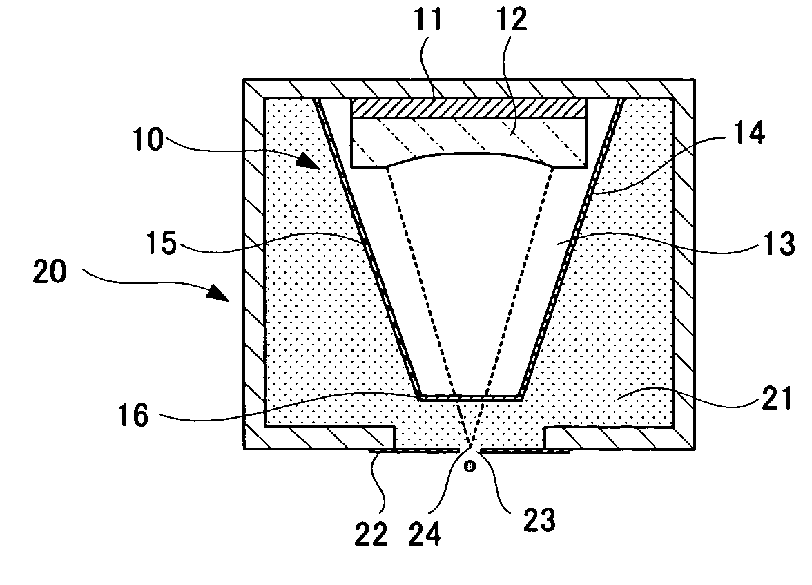
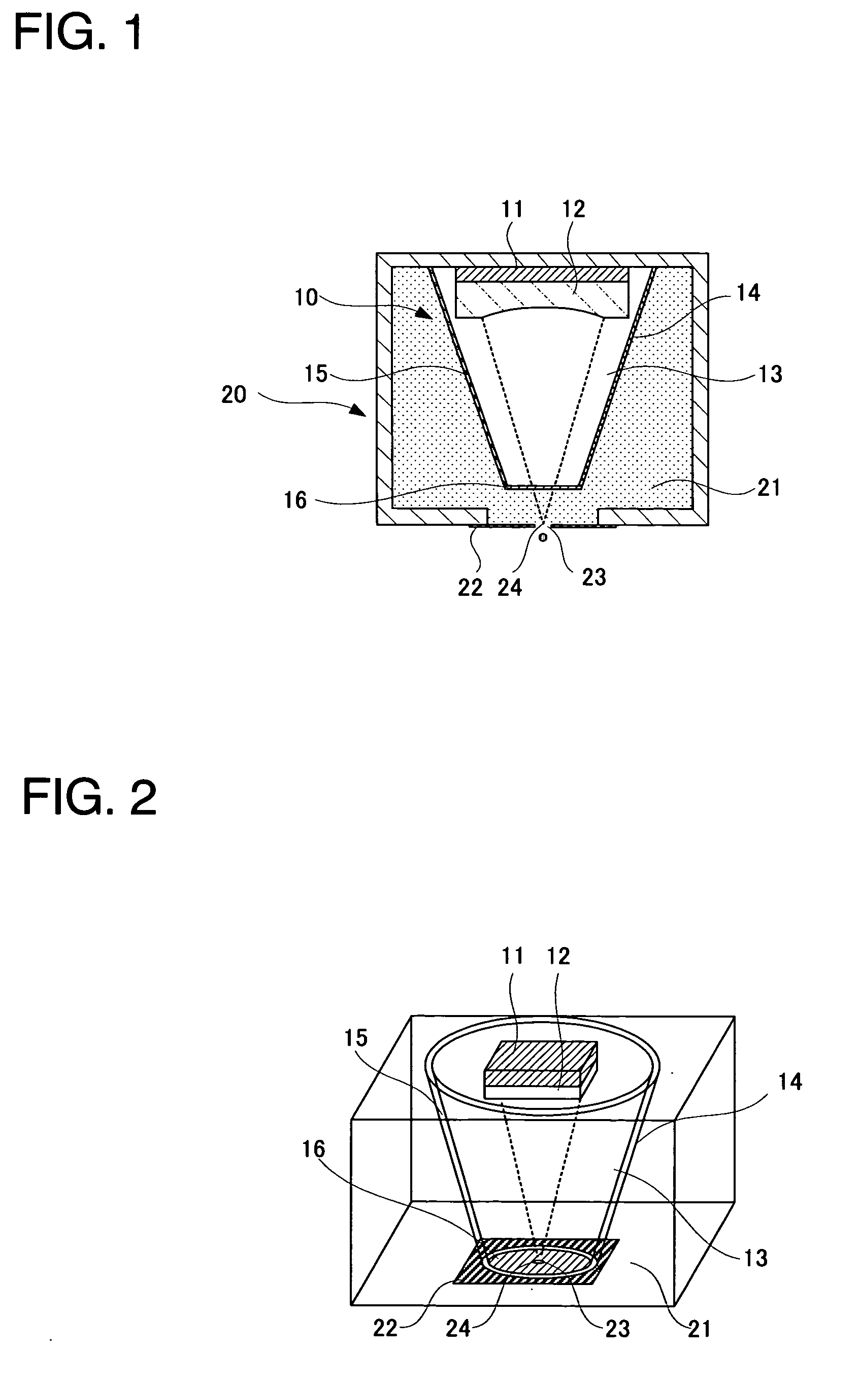
[0033]In the above-stated first embodiment, the ultrasonic waves generated at the ultrasonic wave generation member 11 and focused by the ultrasonic wave focusing member 12 is propagated until in the vicinity of the ultrasonic wave focus point 24 by the ultrasonic wave propagation portion 13. Accordingly, it is possible to suppress an influence even when the ink having the large ultrasonic wave attenuation is used, and to eject the ink drops with less power. Besides, as shown in FIG. 1, a height of the head unit 10 provided inside of the ink chamber 20 relative to the ultrasonic wave traveling direction is constituted to be smaller than a depth of the ink chamber 20 in a parallel direction with the ultrasonic wave traveling direction inside of the ink chamber 20. Consequently, the ink of the ink holding chamber 21 inside of the ink chamber 20 is supplied to the ultrasonic wave focus point 24 not via a pore and so on, and therefore, it becomes possible to supply ink easily and evenly...
second embodiment
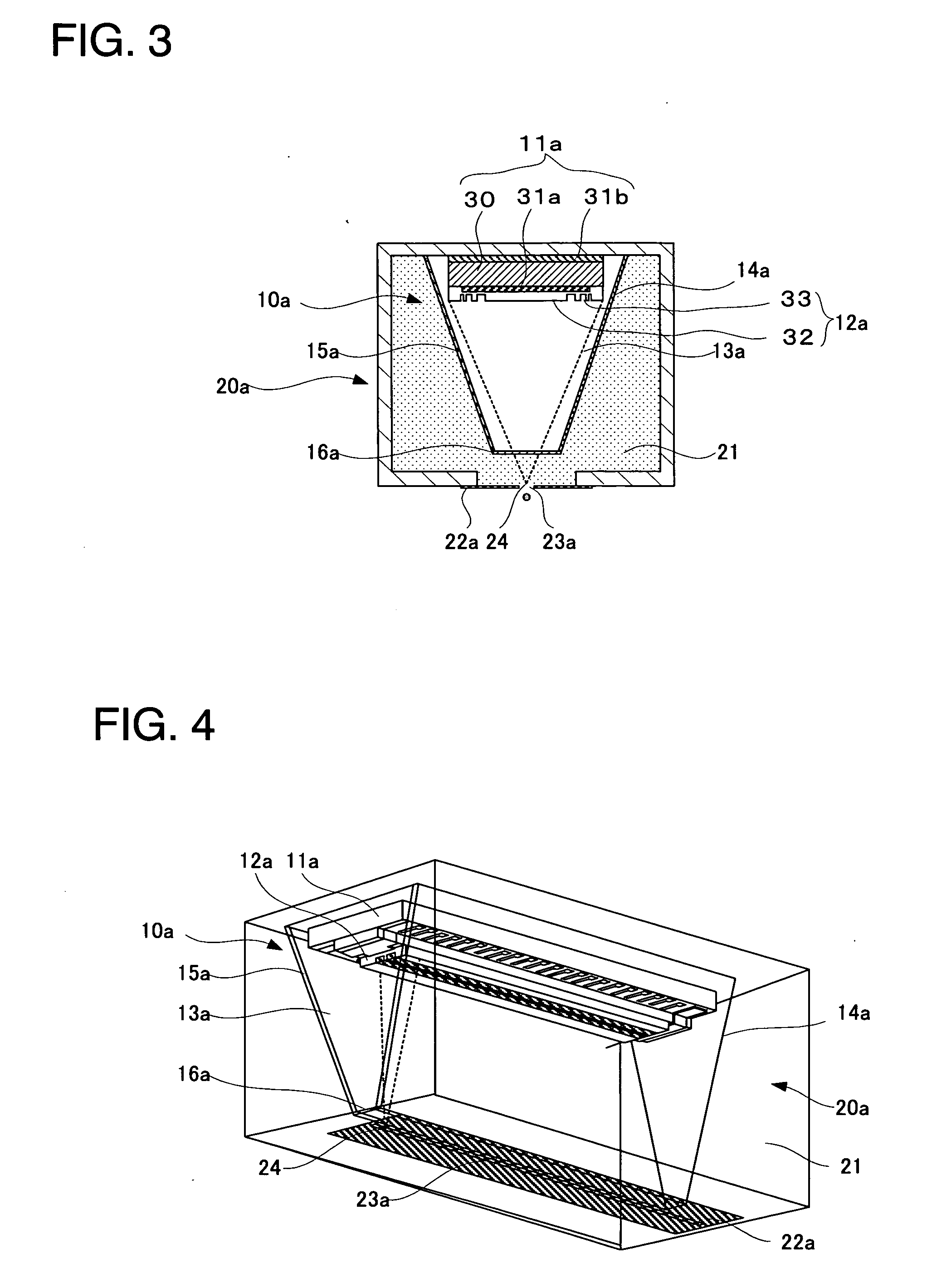
[0035]Incidentally, in the second embodiment, the shape of the container portion 14a of the head unit 10a is the shape of which tip portion side (lower side in FIG. 3 and FIG. 4) becomes narrow as shown in FIG. 3 and FIG. 4, but the shape may be the one of which tip portion side does not become narrow. However, with considering the supply of ink, the shape is preferable to be the one in which an area of the narrow portion (tip portion) between the isolation film 16a and the slit plate 22a becomes small as much as possible.
[0036]FIG. 5 is a view showing a configuration of a third embodiment according to the single head, and FIG. 6 is a view showing a configuration of a fourth embodiment according to the phased array head. The third embodiment is the one in which an ink circulation member 50 is provided to the first embodiment. The ink circulation member 50 is constituted by a pump 51 drawing the ink inside of the ink holding chamber 21 out of the ink chamber 20, an ink tank 52, and a...
PUM
 Abstract
Description
Claims
Application Information
 - R&D
- Intellectual Property
- Life Sciences
- Materials
- Tech Scout
- Unparalleled Data Quality
- Higher Quality Content
- 60% Fewer Hallucinations
Browse by: Latest US Patents, China's latest patents, Technical Efficacy Thesaurus, Application Domain, Technology Topic, Popular Technical Reports.
© 2025 PatSnap. All rights reserved.Legal|Privacy policy|Modern Slavery Act Transparency Statement|Sitemap|About US| Contact US: help@patsnap.com