Eureka AIR delivers breakthrough ideas for toughest innovation challenges, trusted by R&D personnel around the world.
Mobile object image tracking apparatus and method
Active Publication Date: 2009-05-07
KK TOSHIBA
View PDF6 Cites 22 Cited by
Summary
Abstract
Description
Claims
Application Information
AI Technical Summary
This helps you quickly interpret patents by identifying the three key elements:
Problems solved by technology
Method used
Benefits of technology
[0011]In accordance with an aspect of the invention, there is provided a mobile object image tracking apparatus comprising: at least one rotary unit configured to rotate about at least one axis; a camera sensor configured to photograph a mobile object to acquire image data, the camera sensor being supported by the rotary unit; a first detection unit configured to detect a tracking error as a tracking error detection value, based on the image data, the tracking error being a deviation from a center of a field of view of the camera sensor; a second detection unit configured to detect an angle of the rotary unit; an estimation unit configured to estimate the tracking error as a tracking error estimation value, using the angle and a temporal differe
Problems solved by technology
In the above mobile object image tracking systems, their object tracking velocity is limited by the field of view of a camera sensor employed.
Namely, unless a tracking error that occurs when the camera sensor photographs a mobile object falls within the field of view, the mobile object will be missed.
Such a tracking error occurs because the camera sensor performs image processing for extracting a tracking error from an image obtained by photography, and hence it is difficult to reduce the interval of photography, i.e., the sampling time, of the camera sensor.
This being so, when the velocity of a mobile object is increased, the object may fall outside the field of view of the camera sensor and become unable to be tracked.
Once thus the mobile object falls outside the field of view, it is difficult to return the same from outside the field of view to inside.
Namely, the sampling time of the control system becomes long, and this adversely affects the tracking performance, with the result that a mobile object falls outside the field of view of the camera sensor because of a tracking delay.
In these techniques, it is difficult to issue an angular velocity instruction that enables a mobile object to be always appropriately returned into the field of view of the camera sensor.
Further, the method of measuring the distance between a target and an image tracking system requires a length-measurement sensor, and costs high.
Therefore, improvements for the above-mentioned tracking delay due to an increase in sampling time cannot be expected.
Method used
Image
Click on the blue label to locate the original text in one second.
Reading with bidirectional positioning of images and text.
Examples
first embodiment
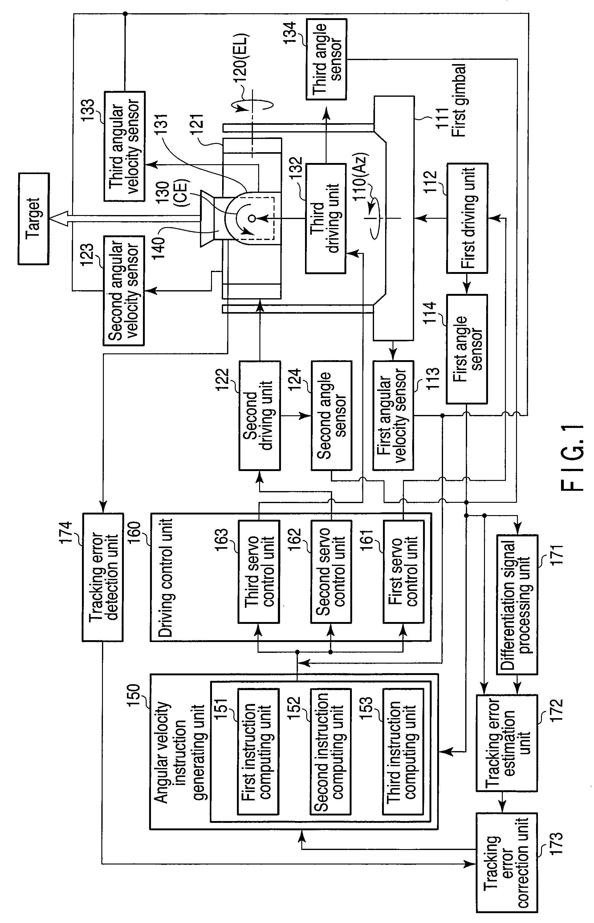
[0025]Referring to FIG. 1, a mobile object image tracking apparatus according to a first embodiment will be described.
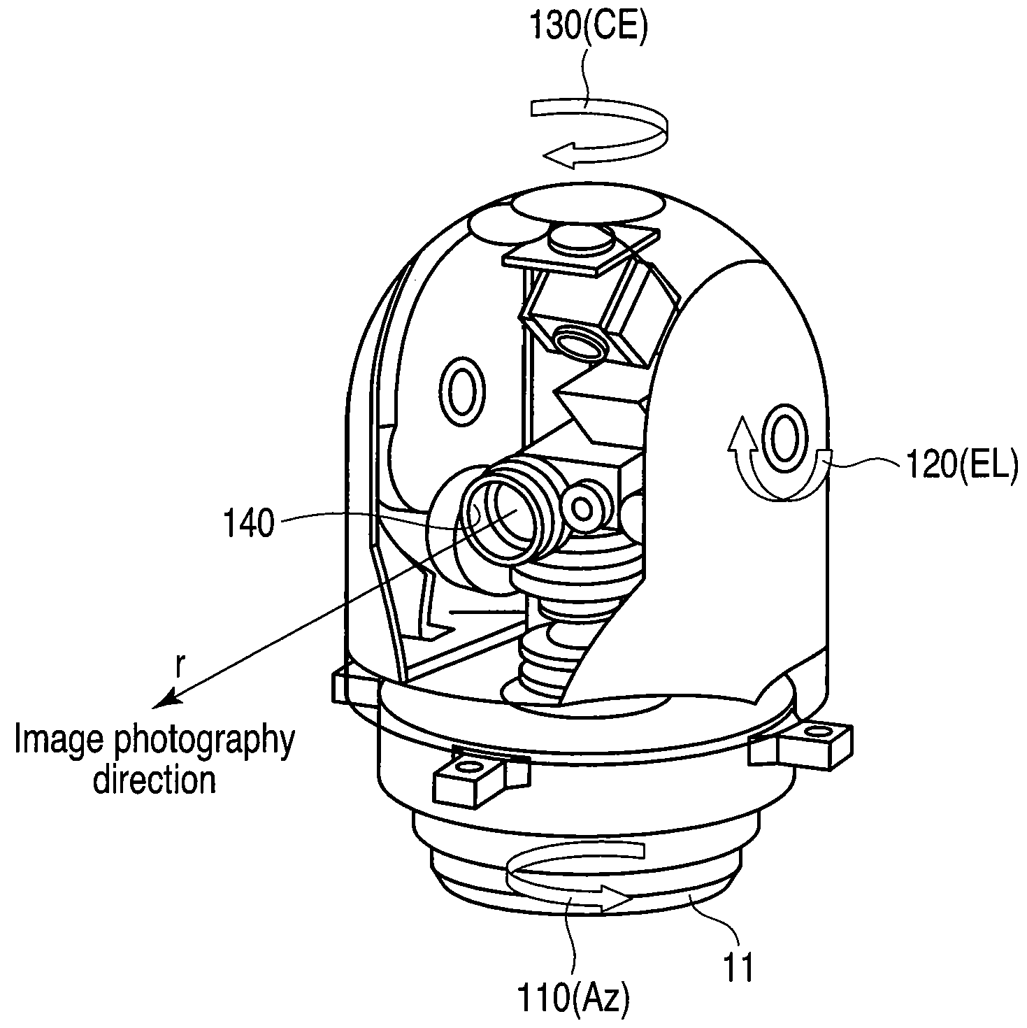
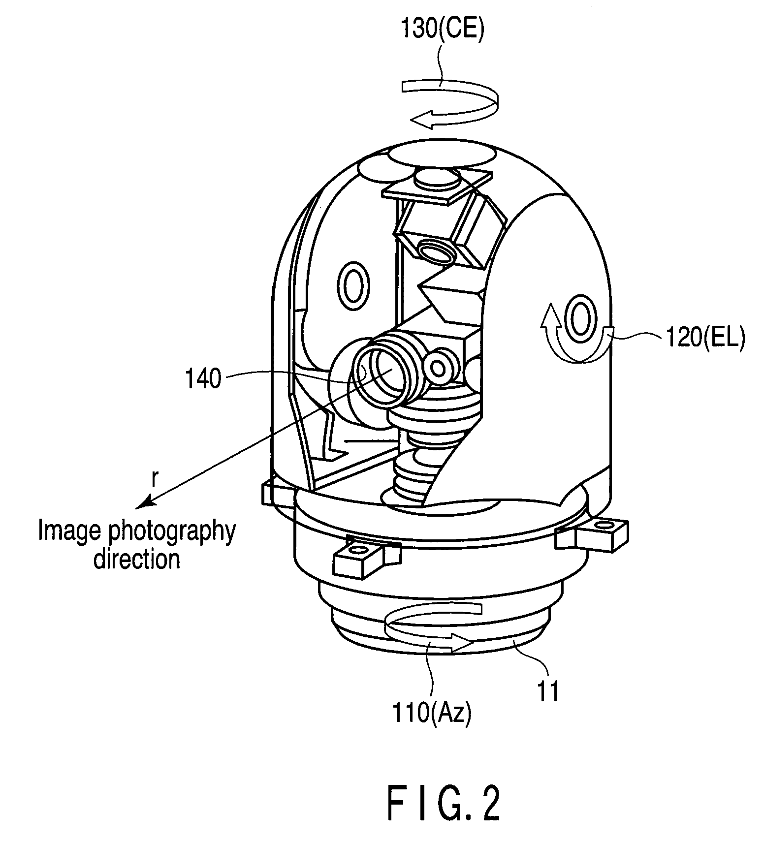
[0026]The mobile object image tracking apparatus of the embodiment comprises first, second and third gimbals 111, 121 and 131, first, second and third driving units 112, 122 and 132, first, second and third angular velocity sensors 113, 123 and 133, first, second and third angle sensors 114, 124 and 134, a camera sensor 140, an angular velocity instruction generating unit 150, a driving control unit 160, a differentiation signalprocessing unit 171, a tracking error estimation unit 172, a tracking error correction unit 173 and a tracking error detection unit 174.
[0027]The angular velocity instruction generating unit 150 includes first, second and third instruction computing units 151, 152 and 153. The driving control unit 160 includes first, second and third servo controllers 161, 162 and 163.
[0028]The first gimbal 111 rotates about a first gimbal axis 110. The secon...
second embodiment
[0070]In a correction control system incorporated in a mobile object image tracking apparatus according to a second embodiment, the sampling time of the camera sensor is measured using, for example, an N-dividing clock for dividing the sampling time of the camera sensor into N divisions, and a tracking error estimation value is computed based on the measured value. The N-dividing clock is used to determine the driving times of the first, second and third gimbals 111, 121 and 131. The mobile object image tracking apparatus of the second embodiment is similar to that of the first embodiment in structure, but differs therefrom in operation. For realizing the different operation, the tracking error correction unit 173 includes a counter for counting clock values.
[0071]Referring to FIG. 10, a description will be given of an operation example of the tracking error correction unit 173 of the mobile object image tracking apparatus according to the second embodiment.
[0072]Firstly, the number...
PUM
Abstract
A mobile objectimage tracking apparatus includes at least one unit rotating about at least one axis, a camera sensor photographing a mobile object to acquire image data, a unit detecting a tracking error as a tracking error detection value, a unit detecting an angle of the rotary unit, a unit estimating the tracking error as a tracking error estimation value, a unit selecting the tracking error detection value when the mobile object falls within the field of view, and selecting the tracking error estimation value when the mobile object falls outside the field of view, a unit computing an angular velocity instruction value used to drive the rotating unit to track the mobile object, a unit detecting an angular velocity of the rotary unit, and a unit controlling the rotating unit to make zero a difference between the angular velocity instruction value and the angular velocity.
Description
CROSS-REFERENCE TO RELATED APPLICATIONS[0001]This application is based upon and claims the benefit of priority from prior Japanese Patent Application No. 2007-288967, filed Nov. 6, 2007, the entire contents of which are incorporated herein by reference.BACKGROUND OF THE INVENTION[0002]1. Field of the Invention[0003]The present invention relates to a mobile object image tracking apparatus and method for enabling a target recognition sensor, such as a camera, to track a target that can move in every direction.[0004]2. Description of the Related Art[0005]In recent years, systems for tracking an object using, for example, an ITV camera, to realize continued monitoring or acquire detailed information have been produced on a commercial basis for protective service equipment employed in major facilities such as airports and manufacturing plants, lifeline facilities such as electric power plants and water networks, and traffic information support systems such as Intelligent TransportSystem...
Claims
Application Information
Patent Timeline
Application Date:The date an application was filed.
Publication Date:The date a patent or application was officially published.
First Publication Date:The earliest publication date of a patent with the same application number.
Issue Date:Publication date of the patent grant document.
PCT Entry Date:The Entry date of PCT National Phase.
Estimated Expiry Date:The statutory expiry date of a patent right according to the Patent Law, and it is the longest term of protection that the patent right can achieve without the termination of the patent right due to other reasons(Term extension factor has been taken into account ).
Invalid Date:Actual expiry date is based on effective date or publication date of legal transaction data of invalid patent.