Oscillating element, manufacturing method of oscillating element, optical scanning device, image forming device and image display device

Inactive Publication Date: 2009-05-07
BROTHER KOGYO KK
View PDF4 Cites 2 Cited by
  • Summary
  • Abstract
  • Description
  • Claims
  • Application Information

AI Technical Summary

Benefits of technology

[0013]That is, the adhesive layer 105 used for adhesion of the piezoelectric element 102 maintains a stable bonded state by an intermolecular force and an anchoring effect which is mechanical bonding induced in an interface between the adhesive layer 105 and a surface to be adhered. However, there may be a case that it is difficult to ensure such a phenomenon depending on properties of a contact surface.
[0014]Particularly, a front surface of the silicon substrate 104 is mirror-finished and hence, the anchoring effect acquired by mechanical bonding cannot be expected whereby there may be a case that the bonding is performed only by the intermolecular force. When the sufficient bonding f

Problems solved by technology

However, there may be a case that it is difficult to ensure s

Method used


Image

  • Oscillating element, manufacturing method of oscillating element, optical scanning device, image forming device and image display device
  • Oscillating element, manufacturing method of oscillating element, optical scanning device, image forming device and image display device
  • Oscillating element, manufacturing method of oscillating element, optical scanning device, image forming device and image display device

Examples


Example

[0027]Preferred embodiments of the present invention are explained in conjunction with drawings hereinafter.

[Constitution of Image Display Device]

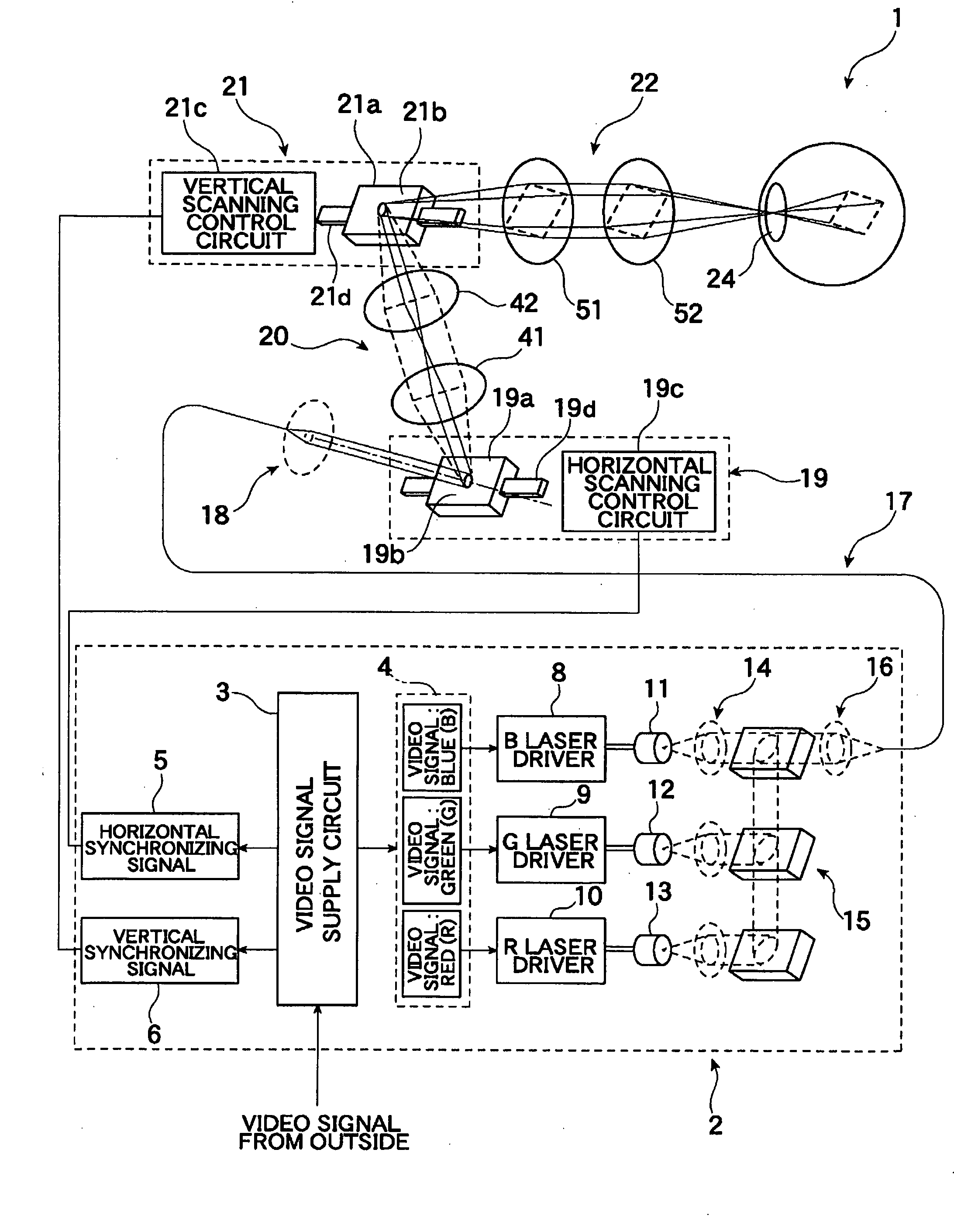
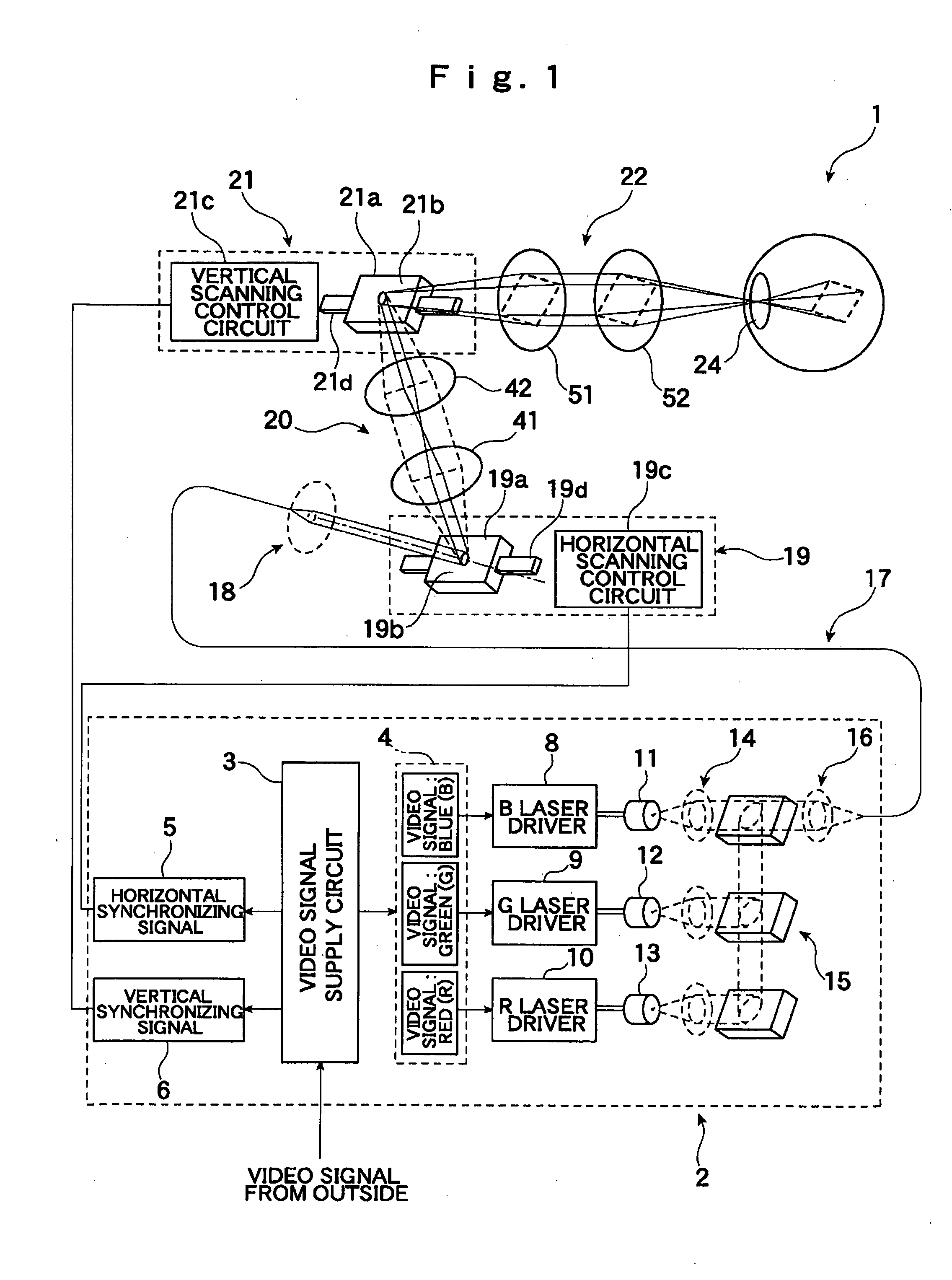
[0028]Hereinafter, one embodiment of an image display device according to the present invention is explained in conjunction with the drawings. First of all, the constitution of a retinal scanning display 1 forming a retinal scanning image display device (retinal scanning image display device) and constituting one example of the image display device according to the present invention is explained in conjunction with FIG. 1.

[0029]As shown in FIG. 1, the retinal scanning display 1 includes a light source unit part 2. The light source unit part 2 include a video signal supply circuit 3 which generates, upon reception of inputting of a video signal from the outside, respective signals which become elements to be used for synthesizing an image in response to the video signal. A video signal 4, a horizontal synchronizing signal 5 and a vertical s...


PUM


Abstract

An oscillating element which can improve the adhesiveness thereof with an actuator is disclosed. In an oscillating element which includes a substrate which is configured to support an oscillation portion in an oscillating manner, and a driving layer which is configured to oscillate the oscillation portion, the driving layer including an adhesive layer formed on a substrate side thereof, an intermediate layer is positioned between the substrate and the driving layer. The intermediate layer is made of a material which allows surface activation bonding with the substrate, and the surface roughness of the intermediate layer on the adhesive layer side is set coarser than the surface roughness of the intermediate layer on the substrate side thus allowing the intermediate layer to easily acquire an anchoring effect with the adhesive layer.

Description

CROSS-REFERENCE TO RELATED APPLICATIONS[0001]The present application is a Continuation-in-Part of International Application No. PCT / JP2007 / 055845 filed on Mar. 22, 2007, which claims the benefits of Japanese Patent Application No. 2006-095527 filed on Mar. 30, 2006.BACKGROUND OF THE INVENTION[0002]1. Field of the Invention[0003]The present invention relates to an oscillating element used for scanning by laser beams or the like, for example, and more particularly to an oscillating element oscillated by an actuator such as a piezoelectric element or the like, a manufacturing method of the oscillating element, an optical scanning device which includes such an oscillating element, an image forming device including such an optical scanning device, and an image display device including such an optical scanning device or an image forming device.[0004]2. Description of the Related Art[0005]Conventionally, as the constitution for oscillating a mirror used in performing scanning by laser beam...

Claims


Application Information

Patent Timeline
IPC IPC(8): H04N5/74H01L41/053H01L41/22B81B3/00B81C1/00G02B26/08G02B26/10G02B27/02H01L41/09H04N1/036
CPCG02B26/105H01L41/0946Y10T29/42Y10S359/90H01L41/313H10N30/2043H10N30/073
Inventor ASAI, NOBUAKI
Owner BROTHER KOGYO KK
Why Eureka
Try Eureka