Solid-state laser gyro having orthogonal counterpropagating modes

a laser gyro and orthogonal technology, applied in the direction of speed measurement using gyroscopic effects, instruments, surveying and navigation, etc., can solve the problems of certain type of laser gyro construction technical difficulties, excluded use of such a device in transmission, and gaseous nature of the amplifying medium, etc., to achieve the effect of reducing or eliminating the undesirable phase shift

Inactive Publication Date: 2009-05-07
THALES SA
View PDF4 Cites 11 Cited by
  • Summary
  • Abstract
  • Description
  • Claims
  • Application Information

AI Technical Summary

Benefits of technology

[0017]When necessary, optical devices exhibiting a reciprocal effect, such as wave plates or rotators, may be inserted into the cavity to minimize or eliminate the undesirabl...

Problems solved by technology

However, the gaseous nature of the amplifying medium is a source of technical complications when producing the laser gyro, notably because of the high gas purity required and the premature wear of the cavity during its use due, in particular, to gas leakage and to deterioration of the high-voltage electrodes used to establish the population inversio...

Method used


Image

  • Solid-state laser gyro having orthogonal counterpropagating modes
  • Solid-state laser gyro having orthogonal counterpropagating modes
  • Solid-state laser gyro having orthogonal counterpropagating modes

Examples


Embodiment Construction

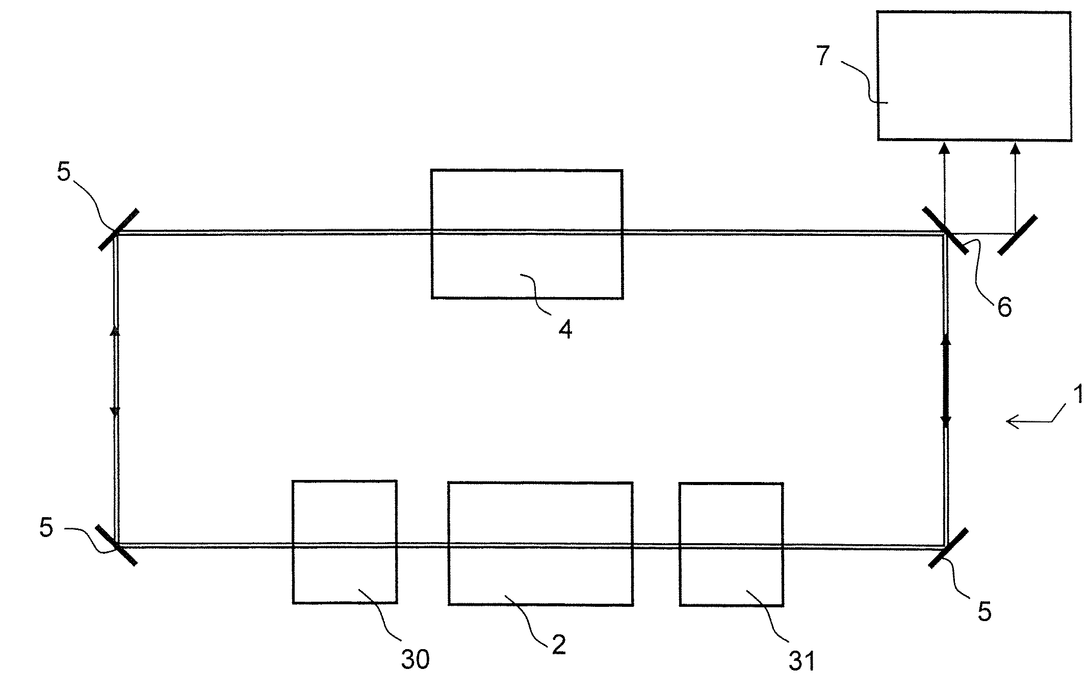
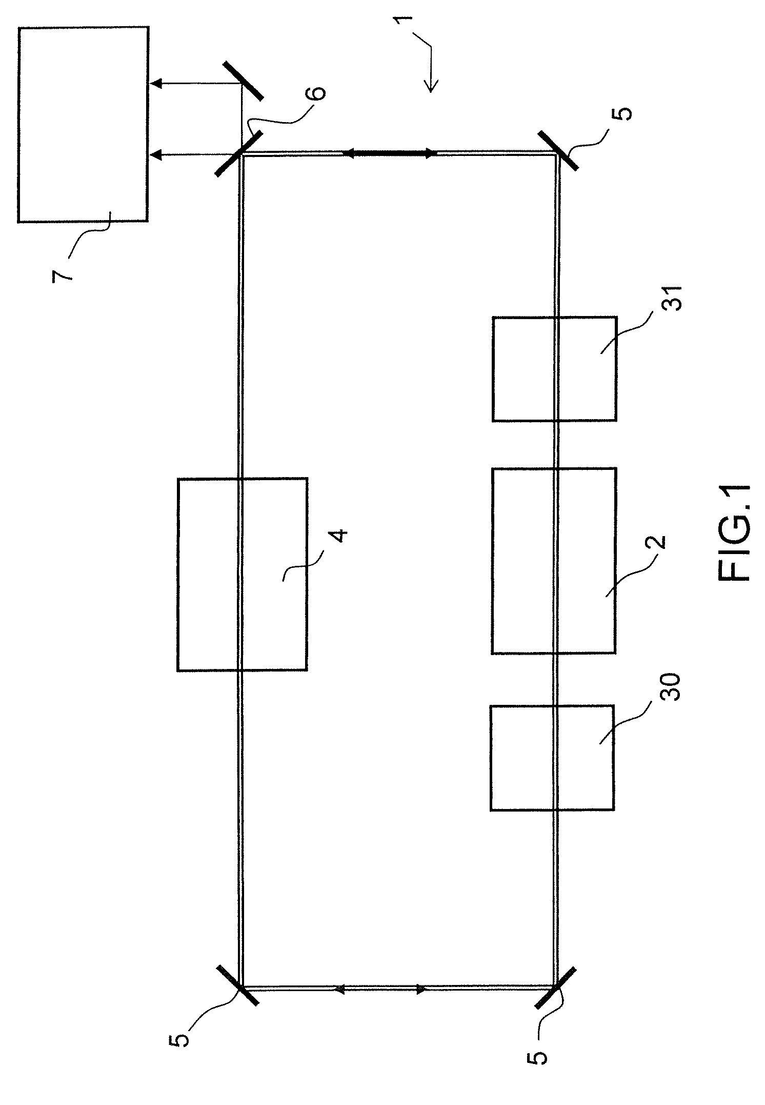
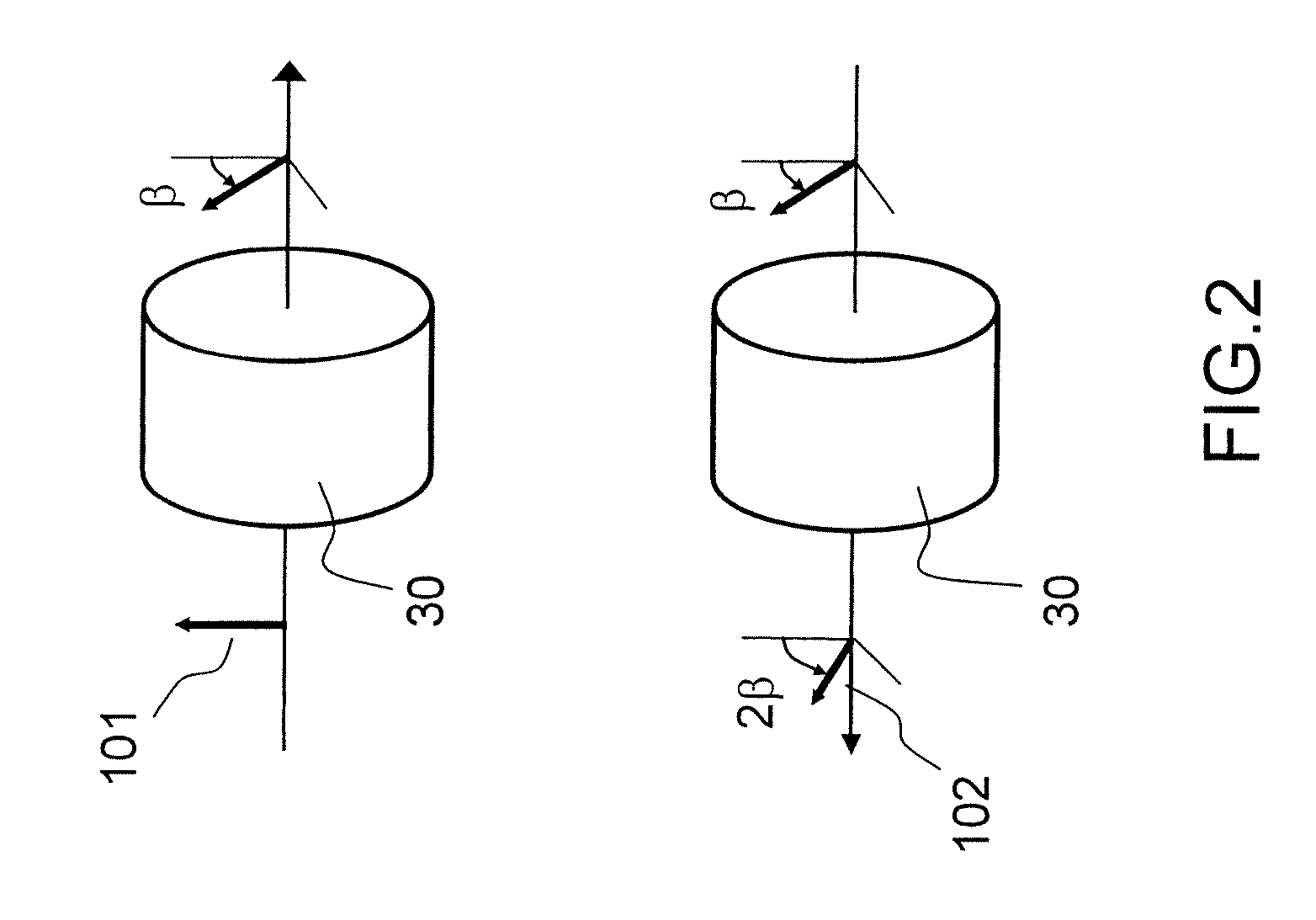
[0025]FIG. 1 shows a diagram of a laser gyro according to the invention. It comprises essentially:[0026]an optical ring cavity 1 consisting of mirrors 5 and a partially transparent plate 6;[0027]a solid-state amplifying medium 2, the optical cavity and the amplifying medium arranged so that a first and second optical wave can propagate in opposite directions within the cavities;[0028]first optical means 4 for imposing a first linear polarization state common to the two counterpropagating optical waves outside the zone containing the amplifying medium 2;[0029]second optical means 30 and 31 for imposing, in the zone containing the amplifying medium and bounded by said elements 30 and 31, a second linear polarization state on the first optical wave and a third linear polarization state on the second optical wave, the third polarization state being perpendicular to the second polarization state; and[0030]a unit 7 for processing and analyzing the two counterpropagating waves for the iner...


PUM


Abstract

The field of the invention is that of solid-state laser gyros used in inertial control units. However, there are certain technical difficulties in producing laser gyros of this type that are due partly to the fact that the counterpropagating waves interfere with each other in the amplifying medium. A laser gyro according to the invention comprises at least one solid-state amplifying medium and an optical ring cavity comprising first optical means for imposing a first linear polarization state common to the two counterpropagating optical waves at the entrance and exit of the zone containing the amplifying medium and second optical means for imposing, within the amplifying medium, a second linear polarization state on the first optical wave and a third linear polarization state on the second optical wave, these polarization states being perpendicular. Thus, all the drawbacks associated with interference are eliminated.

Description

CROSS-REFERENCE TO RELATED APPLICATIONS[0001]The present Application is based on International Application No. PCT / EP2006 / 069449, filed on Dec. 7, 2006, which in turn corresponds to French Application No. 0512604 filed on Jan. 15, 2007, and priority is hereby claimed under 35 USC §119 based on these applications. Each of these applications are hereby incorporated by reference in their entirety into the present application.FIELD OF THE INVENTION[0002]The field of the invention is that of solid-state laser gyros used notably in inertial control units. This type of equipment is used for example for aeronautical applications.BACKGROUND OF THE INVENTION[0003]The laser gyro, developed some 30 years ago, is widely used on a commercial scale at the present time. Its principle of operation is based on the Sagnac effect, which induces a frequency difference Δν between the two optical transmission modes that propagate in opposite directions, called counterpropagating modes, of a bidirectional ...

Claims


Application Information

Patent Timeline
IPC IPC(8): G01C19/66G01C19/64
CPCG01C19/66
Inventor SCHWARTZ, SYLVAINFEUGNET, GILLESPOCHOLLE, JEAN-PAULMIGNOT, AUGUSTINSTEINHAUSSER, BASTIEN
Owner THALES SA
Why Eureka
Try Eureka