Hydrodynamic bearing device and spindle motor equipped with same, and information apparatus

a technology of hydrodynamic bearings and information devices, which is applied in the direction of sliding contact bearings, maintaining head carrier alignment, instruments, etc., can solve the problems of disruption of circulating flow, lubricant leaking out of ventilation holes, and the like, and achieve the effect of suppressing the movement of gas-liquid boundary surfaces, reducing service life, and reducing the size of cross-sectional area

Inactive Publication Date: 2009-05-07
PANASONIC CORP
View PDF2 Cites 2 Cited by
  • Summary
  • Abstract
  • Description
  • Claims
  • Application Information

AI Technical Summary

Benefits of technology

[0075]In this arrangement, the lubricant reservoir is formed so that a cross-sectional area of the first space gradually decreases in size in the peripheral direction from the ventilation hole to the open part of the communicating channel. The flow suppressing part is positioned on an opposite side in the peripheral direction from the lubricant reservoir so as to sandwich the ventilation hole. The flow suppressing part is also formed so as to rapidly reduce a size of the cross-sectional area of the first space in the peripheral direction from the ventilation hole to the open part of the communicating channel.
[0076]Since the capillary force of the lubricant reservoir and the capillary force in the flow suppressing part is thereby balanced even when the interface of the lubricant on the side of the lubricant reservoir tends toward movement in the peripheral direction, there is almost no movement of the interface on the side of the flow suppressing part. As a result, it is possible to suppress movement of the gas-liquid boundary surfaces of the lubricant to the immediate vicinity of the ventilation hole. As a result, the lubricant is prevented from leaking out from the ventilation hole even when vibration or shock is imparted to the hydrodynamic bearing device, and such defects as reduced service life due to outside contamination of the hydrodynamic bearing device or insufficient lubricant can be prevented from occurring.

Problems solved by technology

However, the conventional hydrodynamic bearing device described above has such drawbacks as those described below.
Specifically, in the hydrodynamic bearing device disclosed in the abovementioned publication, although an adequate volume of the lubricant reservoir is maintained, there remains a risk of the lubricant leaking out from the ventilation hole due to shock, vibration, or the like when the gas-liquid boundary parts of the lubricant and the air moves near the ventilation hole due to such causes as component precision issues and other non-design factors.
Specifically, in the stationary state of the hydrodynamic bearing device, although the gas-liquid boundary surfaces is formed substantially uniform and symmetrical about the ventilation hole, when the transition to a rotating state occurs, it is apparent that disruption and the like of the circulating flow occurs due to fluctuations in component precision and other factors, and the gas-liquid boundary surfaces sometimes moves irregularly.
At such times, when an shock, vibration, or the like is imparted in a state in which the gas-liquid boundary surfaces has moved near the ventilation hole, problems occur in that the lubricant easily leaks from the ventilation hole.
The inside of the spindle motor in which the hydrodynamic bearing device is mounted therefore becomes contaminated with lubricant, and there is a risk of such defects as reduced reliability of the device and decreased service life of the bearing due to insufficient lubricant.

Method used


Image

  • Hydrodynamic bearing device and spindle motor equipped with same, and information apparatus
  • Hydrodynamic bearing device and spindle motor equipped with same, and information apparatus
  • Hydrodynamic bearing device and spindle motor equipped with same, and information apparatus

Examples


embodiment 1

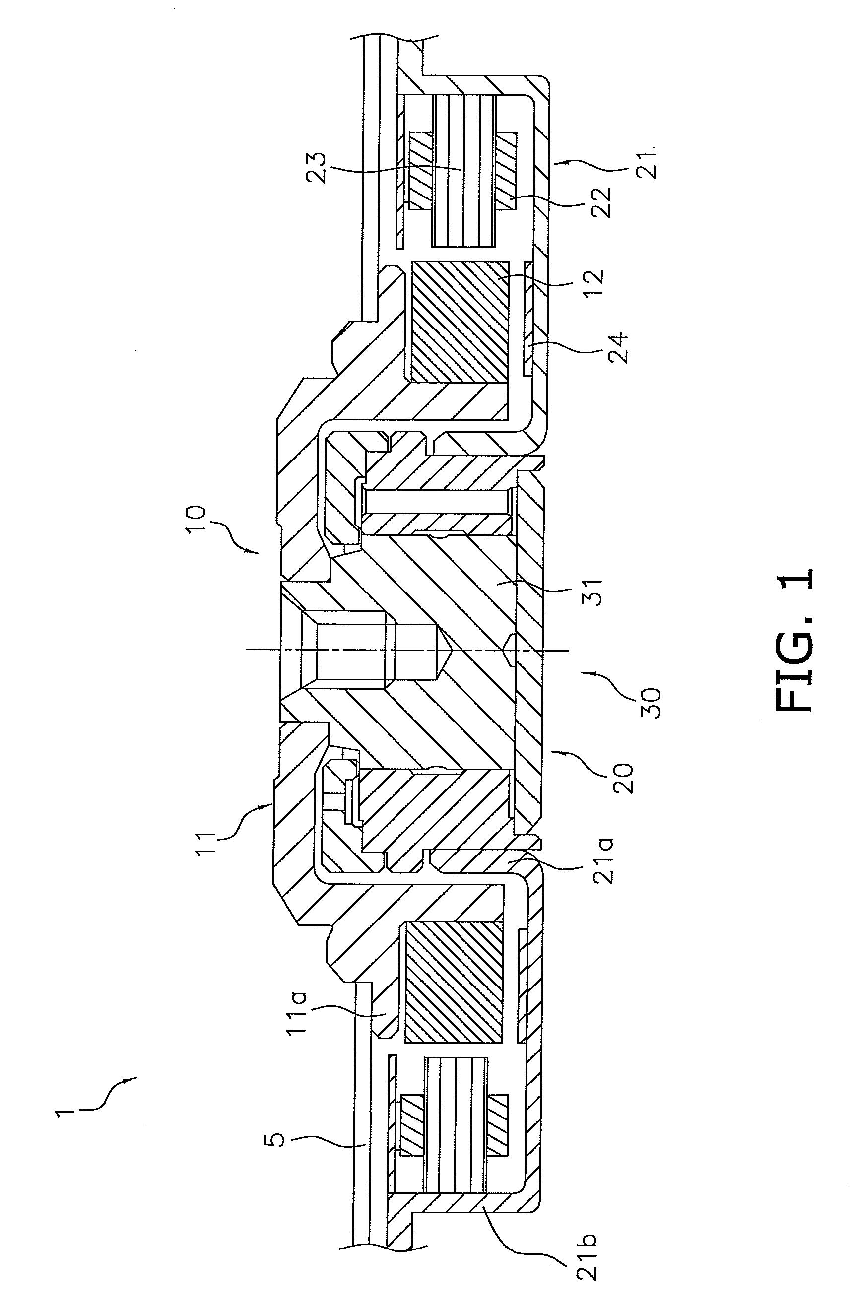
[0114]The spindle motor 1 in which the hydrodynamic bearing device 30 according to an embodiment of the present invention is mounted is as described hereinafter using FIGS. 1 through 9.

[0115]In the description given hereinafter, the vertical direction in FIG. 1 is expressed as the “axial direction,” but this description does not limit the direction in which the hydrodynamic bearing device 30 is actually attached.

[0116][Structure of the Spindle Motor 1]

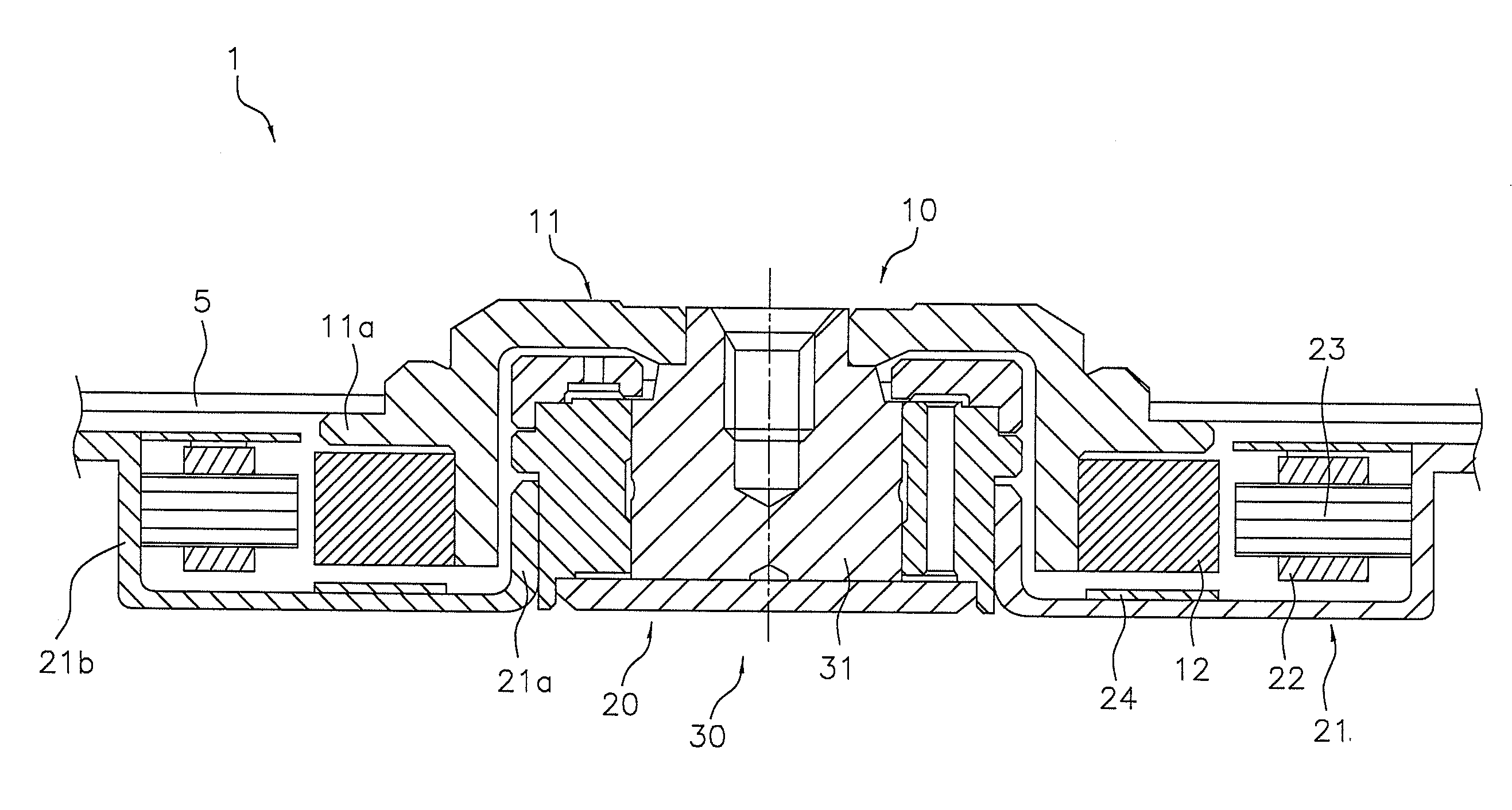
[0117]The spindle motor 1 of the present embodiment as shown in FIG. 1 is a device for rotationally driving a disk-shaped recording disk (recording medium) 5, and primarily comprises a rotary member 10, a static member 20, and the hydrodynamic bearing device 30.

[0118]The rotary member 10 primarily has a hub 11 to which the recording disk 5 is mounted, and a rotor magnet (rotary magnet) 12.

[0119]The hub 11 has a hollow cylinder shape that has a top surface, and is formed by stainless steel (e.g., DHS1) as an iron-based metal material, f...

embodiment 2

[0204]FIG. 23 is a sectional view showing a spindle motor 814 provided with the hydrodynamic bearing device 813 in Embodiment 2 of the present invention.

[0205]For the sake of convenience in the description below, a case will be described in which the open end of the bearing hole 815a of the sleeve 815 is positioned upward, and the closed end is positioned downward, but this positioning is not limited during actual use.

[0206]As shown in FIG. 23, a substantially inverted-cup-shaped hub 817 as a rotary member to which a magnetic recording disk, for example, is fixed on the external periphery thereof is press-fit onto a circular pillar-shaped protruding shaft part 816a that protrudes from a circular bearing hole 815a of a cylindrical sleeve 815 in a shaft 816, and a rotor magnet 819 is attached to the internal periphery of a cylindrical downward-hanging wall part formed on the external periphery of the hub 817. A stator core 821 on which a stator coil 820 is wound is also attached to a ...

embodiment 3

[0248]The hydrodynamic bearing device 1130 according to yet another embodiment of the present invention is as described hereinafter using FIGS. 21A through 22B.

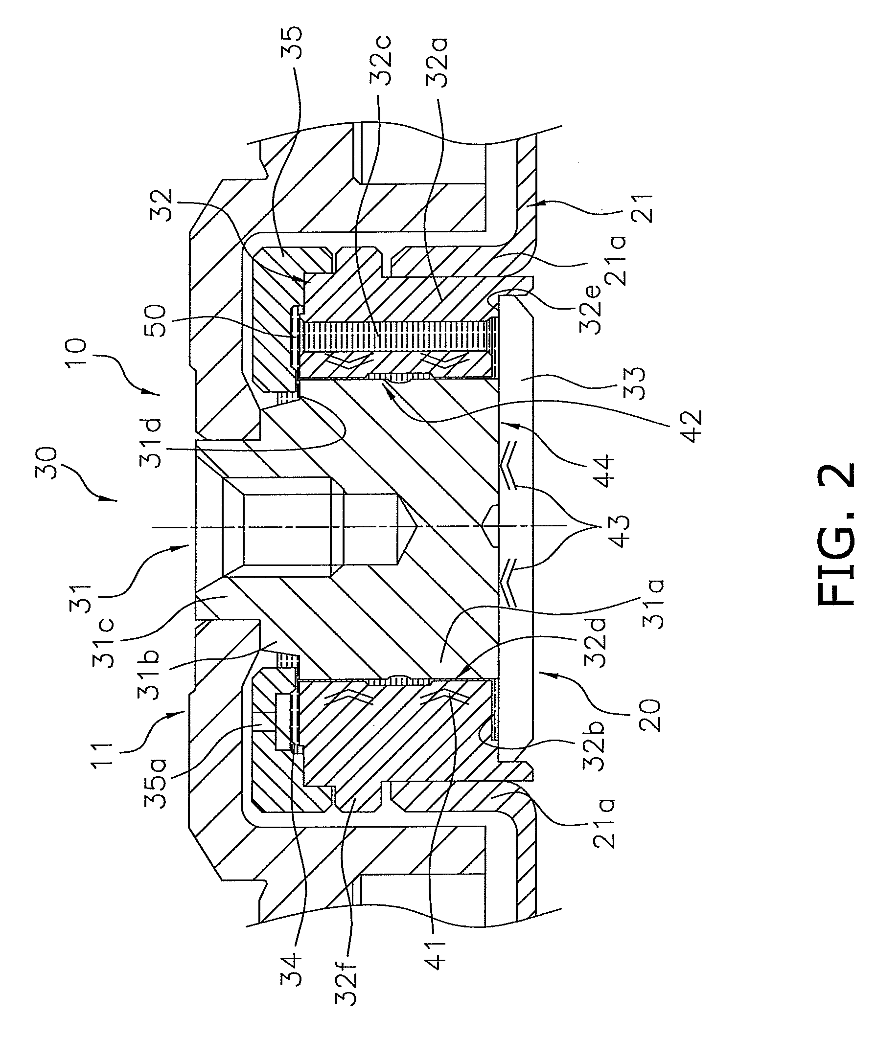
[0249]The hydrodynamic bearing device 1130 of the present embodiment as shown in FIGS. 21(a) and 21(b) differs from the hydrodynamic bearing device 30 of Embodiment 1 in that a substantially cylindrical lubricant reservoir 1150 is provided in the gap between the external peripheral surface of the sleeve 1132 and the internal peripheral surface of the sleeve cover 1135 as well, and the surface on the external peripheral side of the sleeve cover 1135 has a ventilation hole 1112. In other words, the lubricant reservoir 50 of Embodiment 1 described above is formed in the gap between the inner surface of the sleeve cover 35 and the upper end surface of the sleeve 32 opposing in the axial direction. The lubricant reservoir 1150 of the present embodiment, however, is formed in the gap between the internal peripheral surface of the s...


PUM

PropertyMeasurementUnit
tilt angleaaaaaaaaaa
thicknessaaaaaaaaaa

Abstract

A hydrodynamic bearing device (30) comprises a shaft (31), a sleeve (32) in which the shaft (31) is installed so as to be able to rotate in relative fashion, a lubricant (34) filled into a minute gap between the shaft (31) and the sleeve (32), a sleeve cover (35) attached to the upper end surface of the sleeve (32), a lubricant reservoir (50) for retaining the lubricant (34) between the sleeve (32) and the sleeve cover (35), and flow suppressing parts (51a, 51b) formed inside the lubricant reservoir (50) so as to protrude in an axial direction.

Description

CROSS-REFERENCE TO RELATED APPLICATIONS[0001]This application claims priority to Japan Patent Application Nos. 2007-282704 and 2008-063255. The entire disclosures of Japan Patent Application Nos. 2007-282704 and 2008-063255 are hereby incorporated herein by reference.BACKGROUND OF THE INVENTION[0002]1. Field of the Invention[0003]The present invention relates to a hydrodynamic bearing device mounted in a motor for rotationally driving a magnetic disk, optical disk, or other recording disk or polygon mirror or the like, to a spindle motor equipped with the hydrodynamic bearing device, and to an information apparatus.[0004]2. Description of the Related Art[0005]A hydrodynamic bearing device for utilizing hydrodynamic pressure of oil or another lubricant between a shaft and a sleeve and supporting the shaft and sleeve so that the shaft and sleeve can rotate relative to each other has been proposed in the past as a bearing of a spindle motor used in a recording device to rotationally dr...

Claims


Application Information

Patent Timeline
Patent Type & Authority Applications(United States)
IPC IPC(8): G11B17/32F16C32/06H02K5/167
CPCF16C33/103F16C17/107H02K5/1675F16C33/107F16C2370/12
Inventor YANO, HISAAKINISHIYAMA, HIROSHIYOSHIKAWA, YOSEIUENOSONO, KAORU
Owner PANASONIC CORP
Why Eureka
Try Eureka