Wire harness manufacturing method

a manufacturing method and wire harness technology, applied in the field of wire harnesses, can solve the problems of increased manufacturing cost, increased price of the wire harness to which the shape maintenance member or the protector is attached, so as to prevent the deformation prevent the attachment of the covering member, and prevent the effect of unexpected deformation and undesired deformation

Inactive Publication Date: 2013-02-14
AUTONETWORKS TECH LTD +2
View PDF0 Cites 12 Cited by
  • Summary
  • Abstract
  • Description
  • Claims
  • Application Information

AI Technical Summary

Benefits of technology

[0059]In the arrangement using one holding tool, the molded covering member, in the state where it is accommodated in a groove-shaped concave member of the one holding tool, is removed from the molding dies. Accordingly, it is possible to prevent deformation of the covering member by its self weight. Further, when the molded covering member is removed from the molding dies, it is not necessary to directly touch the covering member and it is possible to prevent contact between a foreign material and the covering member. Accordingly, it is possible to prevent unexpected deformation and undesired deformation of the covering member.
[0060]In the arrangement using the other one holding tool, while the predetermined part of the wire harness is cooled, it is possible to continuously add a compression force to the covering member with the one holding tool and the other holding tool. Accordingly, it is possible to prevent the molded covering member from restoring the size and the shape before the molding. Further, it is possible to prevent attachment of the covering member to the molding dies.
[0061]Further, the operation to mold the covering member is simple in comparison with the method of embedding the electric wires in the protector or the shape maintenance member which is an injection molded product. Especially, in the arrangement using the protector or the shape maintenance member which is an injection molded product, the process of manufacturing the protector or the shape maintenance member and the process of attaching the manufactured protector or shape maintenance member to the wire harness are separate processes. On the other hand, according to the method for manufacturing the wire harness according to the present invention, it is possible to cover the electric wires at the same time of molding of the covering member. Accordingly, it is possible to reduce the number of steps in the method for manufacturing the wire harness.
[0062]Further, in comparison with the arrangement where the tape is wrapped around so as to maintain the axial shape of the electric wires in a predetermined shape, the content of the operation is greatly simplified, therefore it is possible to greatly omit the labor and time required in the manufacturing. Further, in comparison with the arrangement where the tape is manually wrapped around, it is possible to stability the quality. The appearance of the wire harness, manufactured by the method for manufacturing the wire harness according to the present invention, is good in comparison with the wire harness in which the tape is wrapped around the electric wires.
[0063]According to the wire harness according to the present invention, the electric wires are closely gathered and closely attached to each other, and no gap is formed (or the gap is small) among the electric wires except unavoidable space. Further, the wire harness has a structure where the electric wires and the covering member are in close contact with each other. It is possible to reduce the cross-sectional size of the predetermined part of the wire harness according to the present invention.
[0064]According to the wire harness according to the present invention, since the central part of the covering member is soft in comparison with the surface layer, the electric wires in the predetermined part, wrapped in the covering member, is elastically in contact. Accordingly, it is possible to prevent occurrence of an impulsive sound or the like between the electric wires and the covering member. Further, in this structure, the covering member also functions as a protector or shock-absorbing material to protect the electric wires from impact or vibration.

Problems solved by technology

First, to manufacture the shape maintenance member or the protector, injection molding dies are required. Since the injection molding dies are generally expensive, the manufacturing cost of the shape maintenance member or the protector and the price are increased. Accordingly, the price of the wire harness to which the shape maintenance member or the protector is attached is also increased. Further, since an operation to attach the shape maintenance member or the protector to the electric wires forming the wire harness is required, the number of steps is increased, and accordingly, there is a possibility of increase in the manufacturing cost.
Further, in the arrangement where the shell-type shape maintenance member or protector is attached to the electric wires forming the wire harness, a gap may exist between the electric wires and the inner peripheral surface of the shape maintenance member or the protector.
Accordingly, when vibration or impact is applied to the wire harness, the electric wires collide with the inner peripheral surface of the shape maintenance member or the protector, and a slapping sound or an impulsive sound occurs.
The occurrence of such slapping sound or impulsive sound may degrade the quality of the vehicle or the like to which the wire harness is applied.
Further, there is a possibility of damage by the collision of the electric wires with the inner peripheral surface of the shape maintenance member or the protector.
However, in this arrangement, since a work operation to provide the shock-absorbing material inside the shape maintenance member or the protector is required, the number of steps is increased, and the manufacturing cost may be increased.
Further, since the number of parts is increased, the cost of the parts may be increased.
However, it is conceivable that the structure disclosed in Japanese Published Unexamined Patent Application No. 2003-197038 has the following problems.
Accordingly, when the press-molded wire harness is removed from the metal dies and conveyed, it may be distorted due to the self weight of the flat circuit body and / or the covering member.
In this manner, there is a probability of undesired deformation of the wire harness after the press molding.
Further, when the covering member is removed from the metal dies in a state where the covering member is not hardened, since pressing forces applied to the contact surface between the covering members are eliminated, the weld strength between the covering members is lowered, and there is a possibility of peeling off of the extension parts.
However, since the press molding is performed in a state where the flat circuit body is held between the two covering members, it is difficult to accurately perform positioning of the flat circuit body, and it is difficult to accurately lead the flat circuit body to the concave member of the metal dies.
Further, when the conventional protector is directed to shape change such as bending after the molding or cooling, there is a possibility of breakage of the protector.
Otherwise, since the rigidity is high, it cannot be shape-changed.
However, since the electric wire forming the wire harness generally has an approximately circular cross-sectional shape, a gap occurs among the electric wires even when the electric wires are closely bundled.
On the other hand, in the arrangement described in Japanese Published Unexamined Patent Application No. 2003-197038, since it is difficult to closely pack the electric wires (as the electric wires are flatly arrayed), it is difficult to reduce the cross-sectional area of the wire harness.
However, in this method, it is difficult to eliminate the gap among the electric wires.
Further, in this method, it takes labor and time in the operation to wrap the tape around the electric wires.
Further, the appearance of the tape-wrapped structure is bad.
Further, when the tape wrapping operation is manually performed, there is a probability of occurrence of variation in quality.

Method used


Image

  • Wire harness manufacturing method
  • Wire harness manufacturing method
  • Wire harness manufacturing method

Examples


first embodiment

[0130]Next, tools used in the method for manufacturing the wire harness according to the present invention will be described.

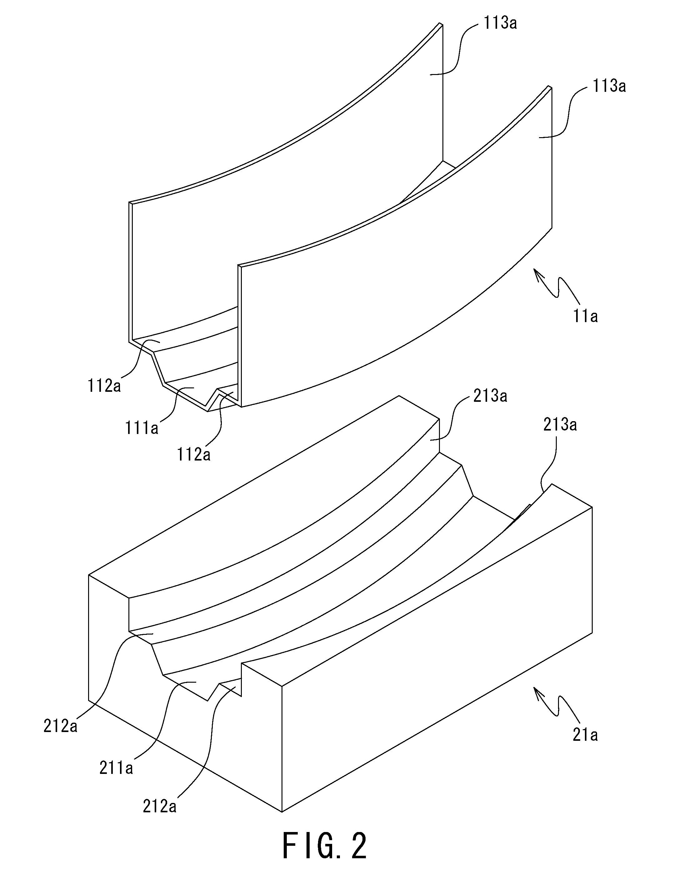
[0131]In the method for manufacturing the wire harness according to the first embodiment of the present invention, a first lower holding tool 11a and a pair of molds including a first upper mold 22a and a first lower mold 21a (e.g. metal dies) are used. FIG. 2 is an external perspective diagram schematically showing structures of the first lower holding tool 11a and the first lower mold 21a, and FIG. 3 is an external perspective diagram schematically showing a structure of the first upper mold 22a. Note that in the first lower holding tool 11a and the first lower mold 21a, the upper side in FIG. 2 is the side facing the first upper mold 22a. In the first upper mold 22a, the upper side in FIG. 3 is the side facing the first lower mold 21a. Hereinbelow, for the sake of convenience of explanation, regarding the first lower holding tool 11a and the first lower mol...

second embodiment

[0228]FIG. 8 is an external perspective diagram schematically showing structures of the second upper mold 22b and the first upper holding tool 12a used in the method for manufacturing the wire harness according to the present invention. In FIG. 8, the upper side in the figure is the side facing the first lower mold 21a. Hereinbelow, for the sake of convenience of explanation, the upper side in the figure will be referred to as the lower side of the second upper mold 22b and the first upper holding tool 12a, and the lower side in the figure will be referred to as the upper side.

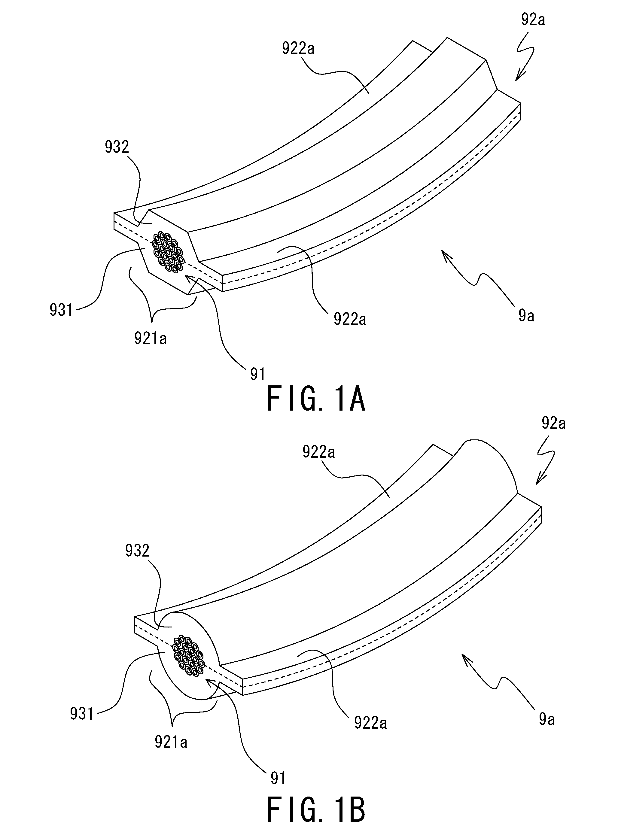
[0229]The first upper holding tool 12a is a tool having a function of pressurizing the first molded body 931 and the second molded body 932 and a function of maintaining the predetermined part of the manufactured first wire harness 9a (especially, the molded covering member 92a) in a predetermined shape (in other words, preventing unexpected deformation or undesired deformation), in the process of manufacturin...

third embodiment

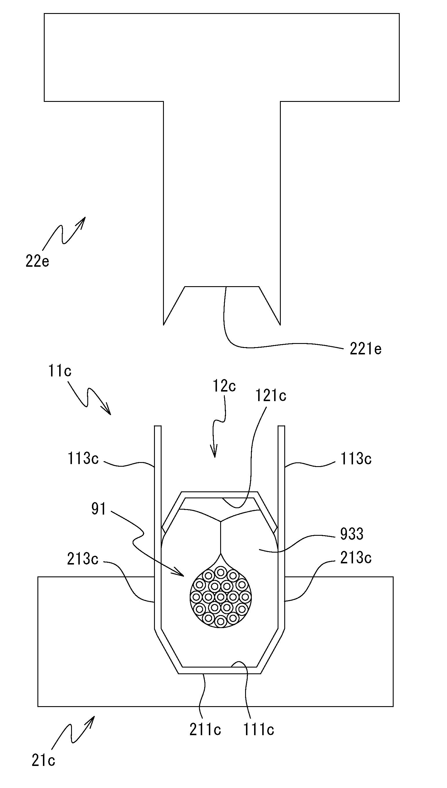
[0277]FIGS. 15 to 17 are cross-sectional diagrams schematically showing predetermined processes of the method for manufacturing the wire harness according to the present invention. Respectively, FIG. 15 is a diagram showing a state where the second upper holding tool 12b and the second lower holding tool 11b, in which the first molded body 931, the predetermined part of the electric wires 91 and the second molded body 932 are provided, is placed on the second lower mold 21b. FIG. 16 is a diagram showing a state where the first molded body 931, the predetermined part of the electric wires 91 and the second molded body 932 are pressurized with the third upper mold 22c and the second lower mold 21b. FIG. 17 is a diagram showing a state where the predetermined part of the manufactured the second wire harness 9b of the present invention, in a state where it is held between the second upper holding tool 12b and the second lower holding tool 11b, is removed from the third upper mold 22c an...


PUM


Abstract

A method for manufacturing a wire harness includes holding a predetermined part of electric wires (91) with first and second molded bodies (931, 932). The first and second molded bodies (931, 932) are placed on a lower holding tool (11a) and are pressurized with lower and upper molds (21a, 22a) having a heater to heat the first and second molded bodies (931, 932) while pressurize them to cover the periphery of the predetermined part of the electric wires (91) with the first and second molded bodies (931, 932). Contact surfaces of the first and second molded bodies (931, 932) are welded. Thereafter, the predetermined part of the electric wires (91) covered with the first and second molded bodies (931, 932) in the state where it is placed on the upper side of the first lower holding tool (11a), is removed from the upper and lower molds (22a, 21a).

Description

BACKGROUND OF THE INVENTION[0001]1. Field of the Invention[0002]The present invention relates to a wire harness, and more particularly, to a method for manufacturing a wire harness and a wire harness provided with a shape maintenance member to maintain a predetermined part of electric wires forming the wire harness in a predetermined shape (this shape maintenance member also has a function as a protector to protect the electric wires forming the wire harness).[0003]2. Description of the Related Art[0004]In a vehicle such as an automobile, a wire harness to mutually connect electric devices, electronic devices and the like is provided. Since the wire harness is arranged along a predetermined route inside the vehicle or the like, in some cases, the wire harness is formed to have a predetermined shape at a manufacturing stage to facilitate the arrangement of the wire harness. For example, the wire harness is formed to have a shape corresponding to the shape of the route in which the wi...

Claims


Application Information

Patent Timeline
Patent Type & Authority Applications(United States)
IPC IPC(8): H01R43/00H02G3/02
CPCB60R16/0215Y10T29/49117B29C43/18
Inventor MURATA, ATSUSHIHIRANO, NOBUYUKISATO, OSAMU
Owner AUTONETWORKS TECH LTD
Why Eureka
Try Eureka