Valve

Inactive Publication Date: 2014-11-06
ERLS MINING
View PDF14 Cites 2 Cited by
  • Summary
  • Abstract
  • Description
  • Claims
  • Application Information

AI Technical Summary

Benefits of technology

[0017]The seal may include an outer surface which abuts an inner surface of the housing and an inner surface which defines a short passage of generally reducing cross-sectional size proceeding from an interior of the housing towards the inlet. The inner surface may have a generally conical shape and may include at least one and preferably at lea

Problems solved by technology

A seal and a valve member of a pinch-type valve, and of a quarter-turn valve such as a ball, butterfly and taper plug valve, are prone to erosion damage when actuated against a high differential pressure particularly in an abrasive medium such as a slurry.
In a valve of conventional construction coupling flanges which are provided on the valve increase in size and cost as the designed operating pressure of the valve increases.
An unfortunate consequence of this type of construction is th

Method used


Image

  • Valve
  • Valve
  • Valve

Examples


Example

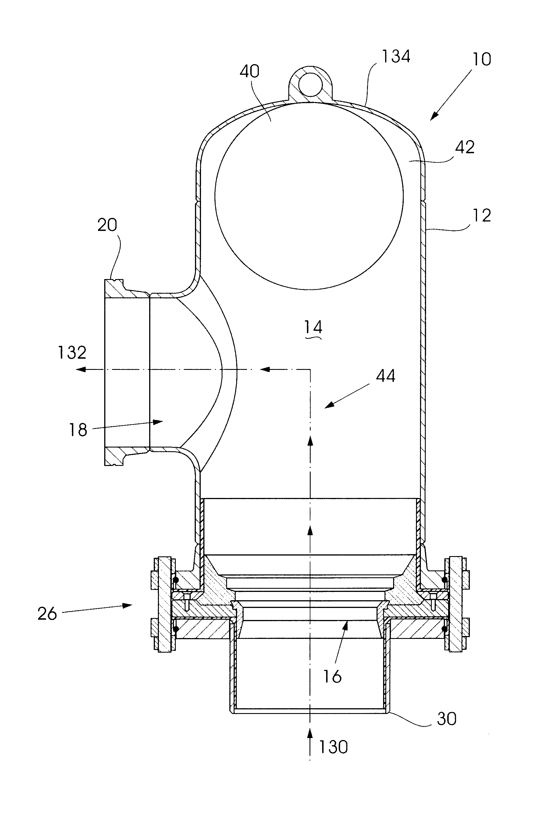
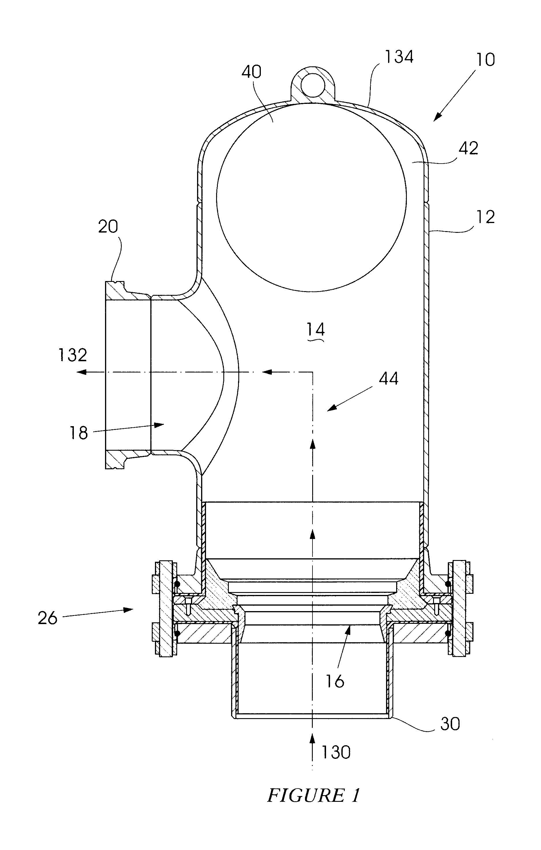
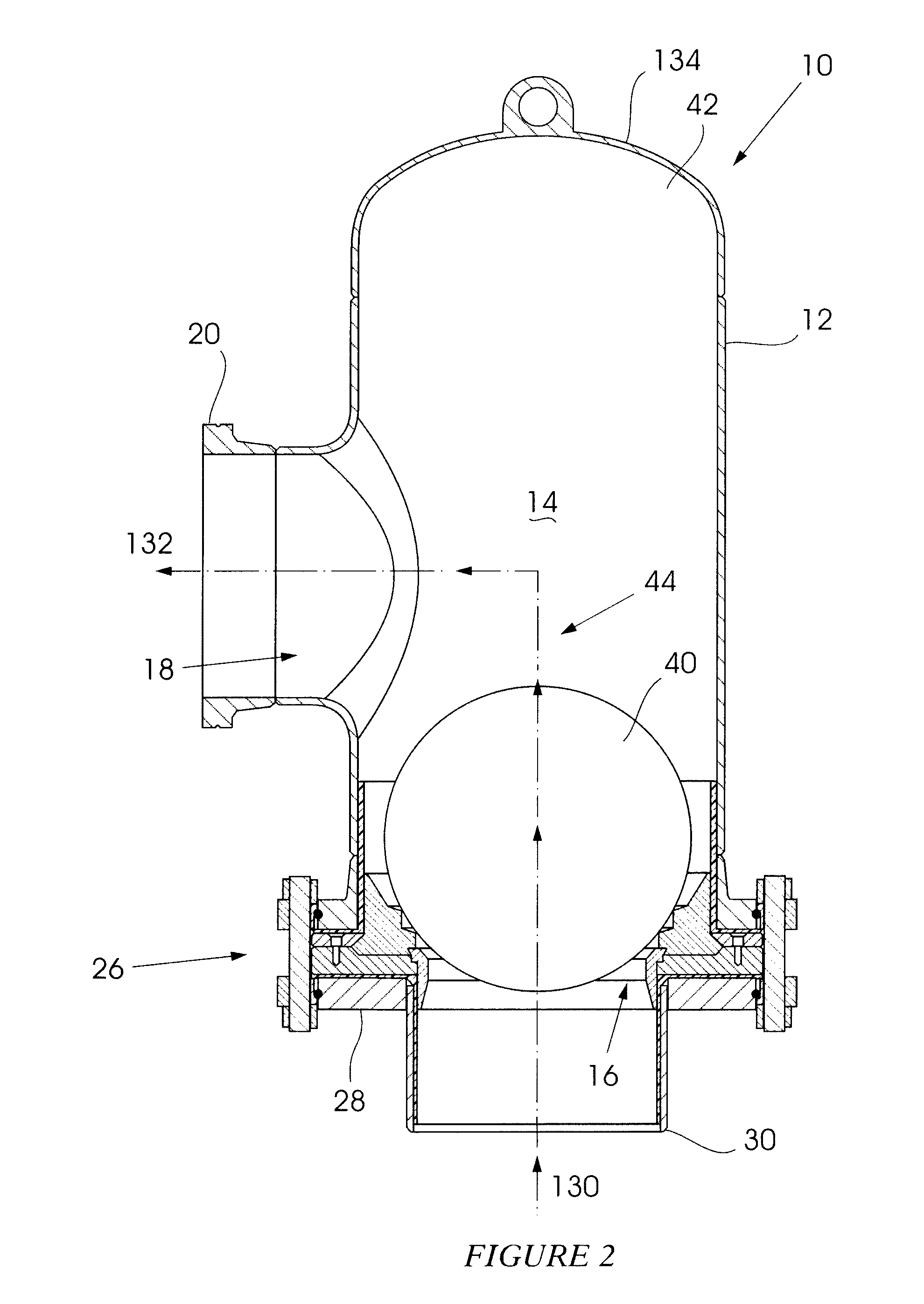
[0033]FIGS. 1 and 2 of the accompanying drawings are views in cross-section and from one side of a valve 10 according to a first form of the invention in an open configuration, and in a closed configuration, respectively.

[0034]The valve includes a housing 12 in which is formed a chamber 14 which has an inlet 16 and an outlet 18. A flange 20 at the outlet is used to couple the valve to a downstream pipe (not shown). The flange 20 may be of a conventional construction but preferably has a construction which is similar to that described herein with reference to a flange at the inlet.

[0035]A flange structure 26, described hereinafter in greater detail with reference particularly to FIG. 4, is used to couple the inlet 16 to an externally grooved flange 28 which is welded to a pipe 30. The flange structure 26 is attached to the housing 12.

[0036]The chamber cross-sectional area is greater than the cross-sectional area of the inlet to allow for a slight reduction in the velocity of fluid fl...


PUM


Abstract

A valve with a housing (12) in which is formed a chamber (14), an inlet (16) to the chamber, an outlet (18) from the chamber which is at a right angle relative to the inlet, a metallic valve seat (90) at the inlet, a resilient valve seal (100) mounted to the valve seat at the inlet and a spherical valve member (40) inside the chamber.

Description

BACKGROUND OF THE INVENTION[0001]This invention relates to a one-way valve which is suitable for use in a harsh environment and which is capable of functioning at a high pressure and at a high frequency of operation.[0002]The applicant is aware of a one-way valve which is based on the use of a spherical valve member. In one application two of these valves are used with a diaphragm pump member. One valve is upstream of the diaphragm and the other is downstream of the diaphragm. Effectively the valves run in series with each other and the diaphragm is between the valves.[0003]The applicant's international patent application number PCT / ZA2009 / 000071 entitled Pumping System (referred to hereinafter as the “earlier specification”, the content of which is hereby incorporated into this specification) describes a bladder-based arrangement capable of operating under high pressures which is suited, inter alia, for the pumping of abrasive slurries and the like. The pumping operation is control...

Claims


Application Information

Patent Timeline
IPC IPC(8): F16K15/04
CPCF16K15/04
Inventor WOOD, RICHARD ROYBREDIN, MURRAY
Owner ERLS MINING
Why Eureka
Try Eureka