Static eliminator and electric discharge module

a technology of electric discharge module and static eliminator, which is applied in the direction of electrostatic charge, electrical apparatus, corona discharge, etc., can solve the problems of increased maintenance cost of static eliminator for ensuring normal ion generation, limited installation place of static eliminator, and difficult maintenance work, so as to facilitate cleaning and enhance the maintainability of static eliminator

Inactive Publication Date: 2009-05-07
KOGANEI
View PDF3 Cites 18 Cited by
  • Summary
  • Abstract
  • Description
  • Claims
  • Application Information

AI Technical Summary

Benefits of technology

[0008]It is hence an object of the present invention to realize replacement of electric discharge needles in the static eliminator, and to enhance the maintainability of the device.
[0014]According to the present invention, in a case body having a blow duct for blowing out an ionized air, an electric discharge module having an electric discharge needle substrate provided with a plurality of electric discharge needles is detachably mounted, and by dismounting the electric discharge module, the electric discharge needles may be easily cleaned or the electric discharge needles may be replaced. As a result, the maintainability of the static eliminator is enhanced.

Problems solved by technology

However, to replace the worn discharge electrodes with new discharge electrodes, the large-sized detachable unit must be replaced, and the detachable unit is discarded together with the high-voltage supply unit, and since the usable high-voltage supply unit is discarded at the same time, and the maintenance cost of the static eliminator for ensuring normal ion generation is increased.
Still worse, a detaching direction of the detachable unit from the main body case is at right angle to the air flow, and a drawing space for the detachable unit is needed in the dismounting area of the detachable unit, and not only the installation place of the static eliminator is limited, but also the maintenance work is difficult.

Method used


Image

  • Static eliminator and electric discharge module
  • Static eliminator and electric discharge module
  • Static eliminator and electric discharge module

Examples


Embodiment Construction

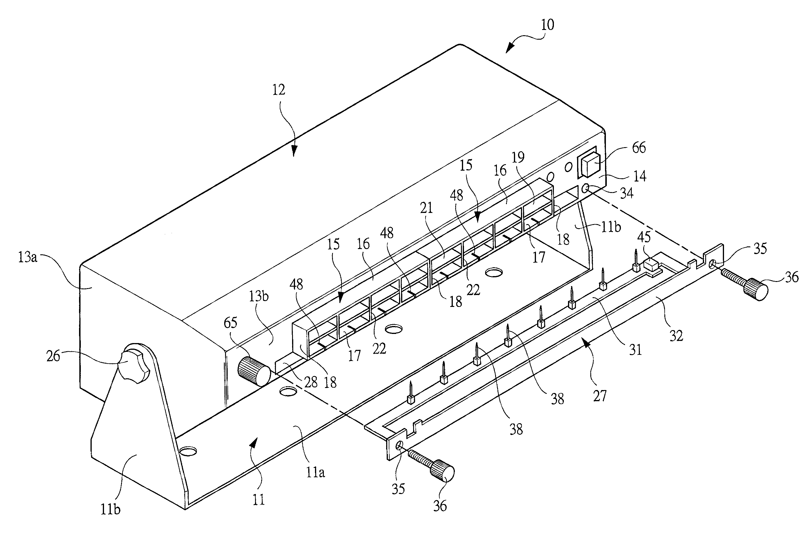
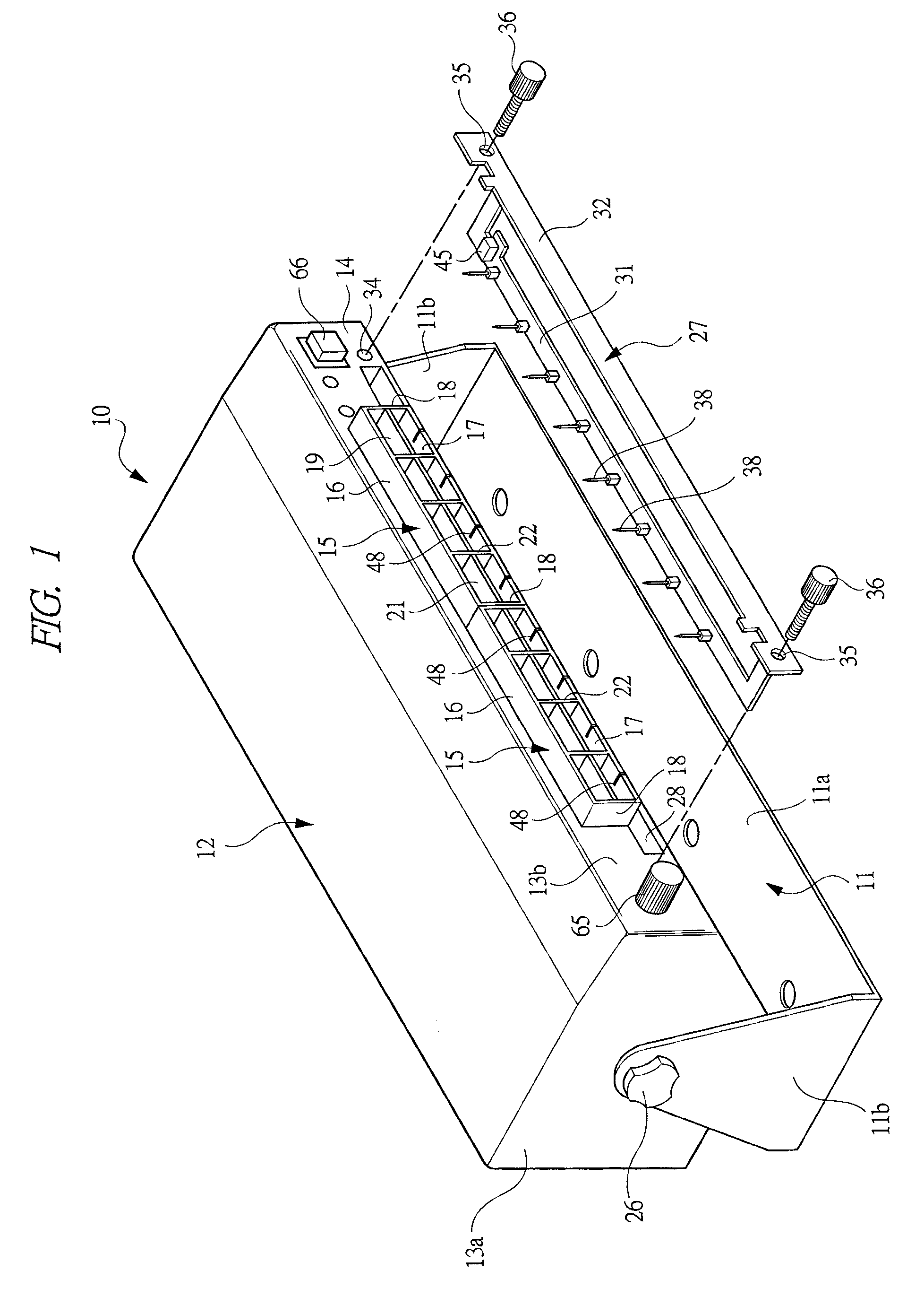
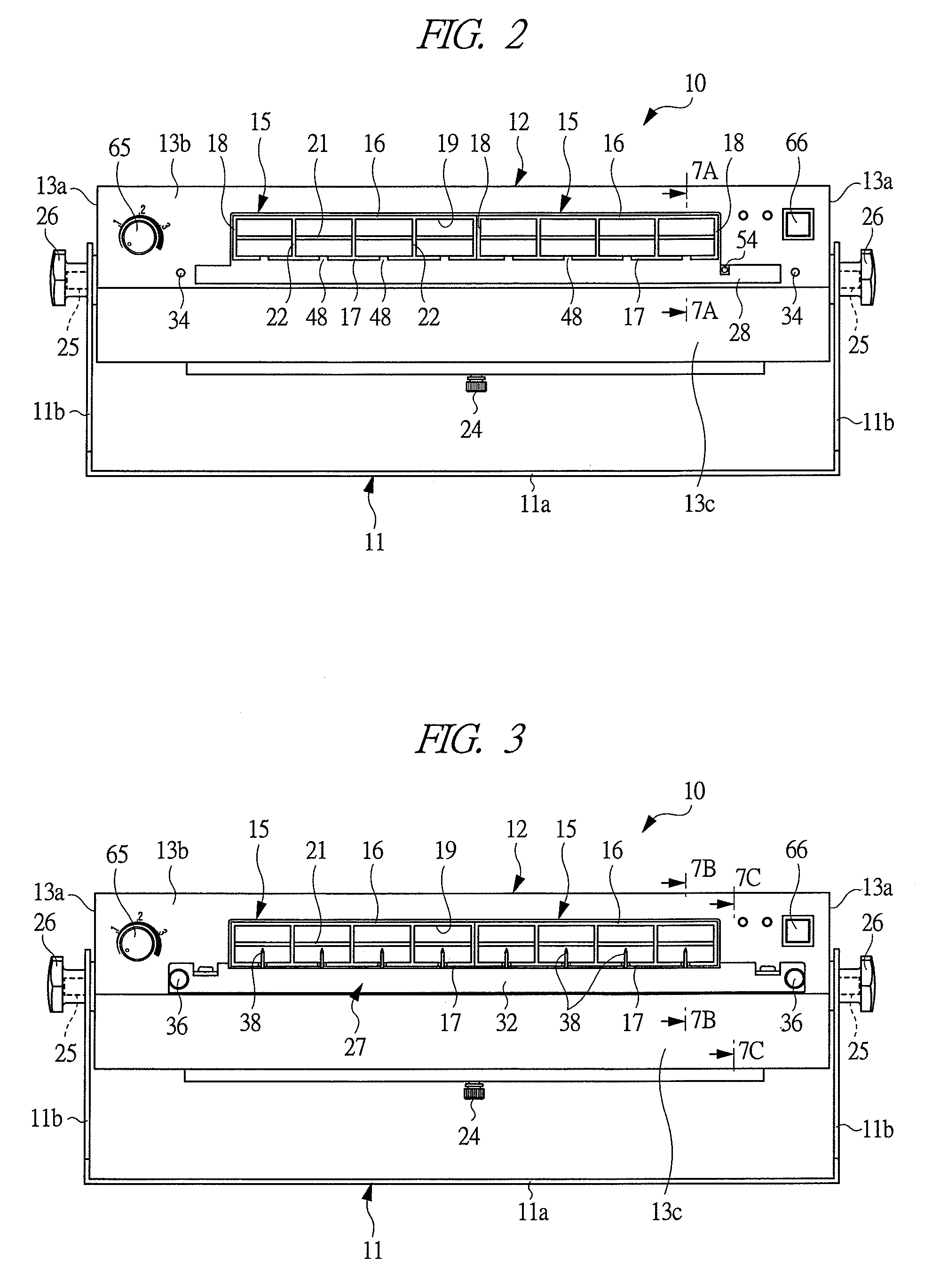
[0027]An embodiment of the present invention is specifically described below while referring to the accompanying drawings. As shown in FIG. 1, this static eliminator 10 has a holder 11 and a case body 12. The holder 11 includes a base part 11a, and a support part 11b formed integrally at both ends of the base part 11a, substantially at right angle to the base part 11a, and is formed by bending a metal plate. The case body 12 is formed of resin or metal material, and is formed like a box on the whole. Both end walls 13a of the case body 12 are rotatably supported to the support part 11b, and the outer side of a sidewall 13b substantially at right angle to the end wall 13a is formed as an air blow side 14. The sidewall 13b has a blow duct 15 for blowing out an ionized air being opened toward the air blow side 14, and a part of the blow duct 15 projects outward from the air blow side 14.

[0028]The case body 12 is provided with two blow ducts 15, and each blow duct 15 has longer sides 16...


PUM


Abstract

This static eliminator is used for eliminating static electricity from an object by ionizing the air to be blown to a charged object, and has a case 12 body provided with an air blow duct 15 for blowing out an ionized air, and an electric discharge module 27 being mounted detachably on the case body 12. The electric discharge module 27 has an electric discharge needle substrate 31 having a plurality of electric discharge needles 38 arranged straightly, and a surface panel 32 detachably mounted on the case body, and the electric discharge module 27 is mounted on the case body 12 by mean of a mounting screw member 36 in the portion of the surface panel 12. By dismounting the electric discharge module 27 from the case body 12, the electric discharge needles can be replaced.

Description

TECHNICAL FIELD[0001]The present invention relates to a static eliminator for eliminating static electricity from electrostatically charged electronic components or other objects, and an electric discharge module.BACKGROUND ART[0002]When manufacturing or assembling an electronic component, if a tool used for manufacturing or assembling an electronic component is charged with a static electricity, foreign matter such as dust may stick to the electronic component, and a defective product may be produced, or the electronic components in the transfer process may attract and contact with each other, and may not be transferred smoothly. Accordingly, by using a static eliminator known as ionizer or ion generator, the electrostatically charged portions or components are treated by blowing an ionized air. To ionize the air by an electric energy, a high voltage is applied to a needle-like discharge electrode, a non-uniform electric field is generated around the discharge electrode, and a coro...

Claims


Application Information

Patent Timeline
Patent Type & Authority Applications(United States)
IPC IPC(8): H05F3/00
CPCH01T23/00H01T19/04
Inventor ONEZAWA, KAZUYOSHIFUKADA, YOSHINARIENOMOTO, YOSUKE
Owner KOGANEI
Why Eureka
Try Eureka