Variable Pump

Inactive Publication Date: 2009-05-07
HOT WATER INNOVATIONS
View PDF9 Cites 4 Cited by
  • Summary
  • Abstract
  • Description
  • Claims
  • Application Information

AI Technical Summary

Benefits of technology

[0026]This invention may also be said broadly to consist in the parts, elements and features referred to or indicated in the specification of the application, individually or collectively, and any or all combinations of any two or more sa

Problems solved by technology

While successful in providing some variability in pump operations, these prior art systems can be prohibitively costly.

Method used


Image

  • Variable Pump
  • Variable Pump
  • Variable Pump

Examples


Embodiment Construction

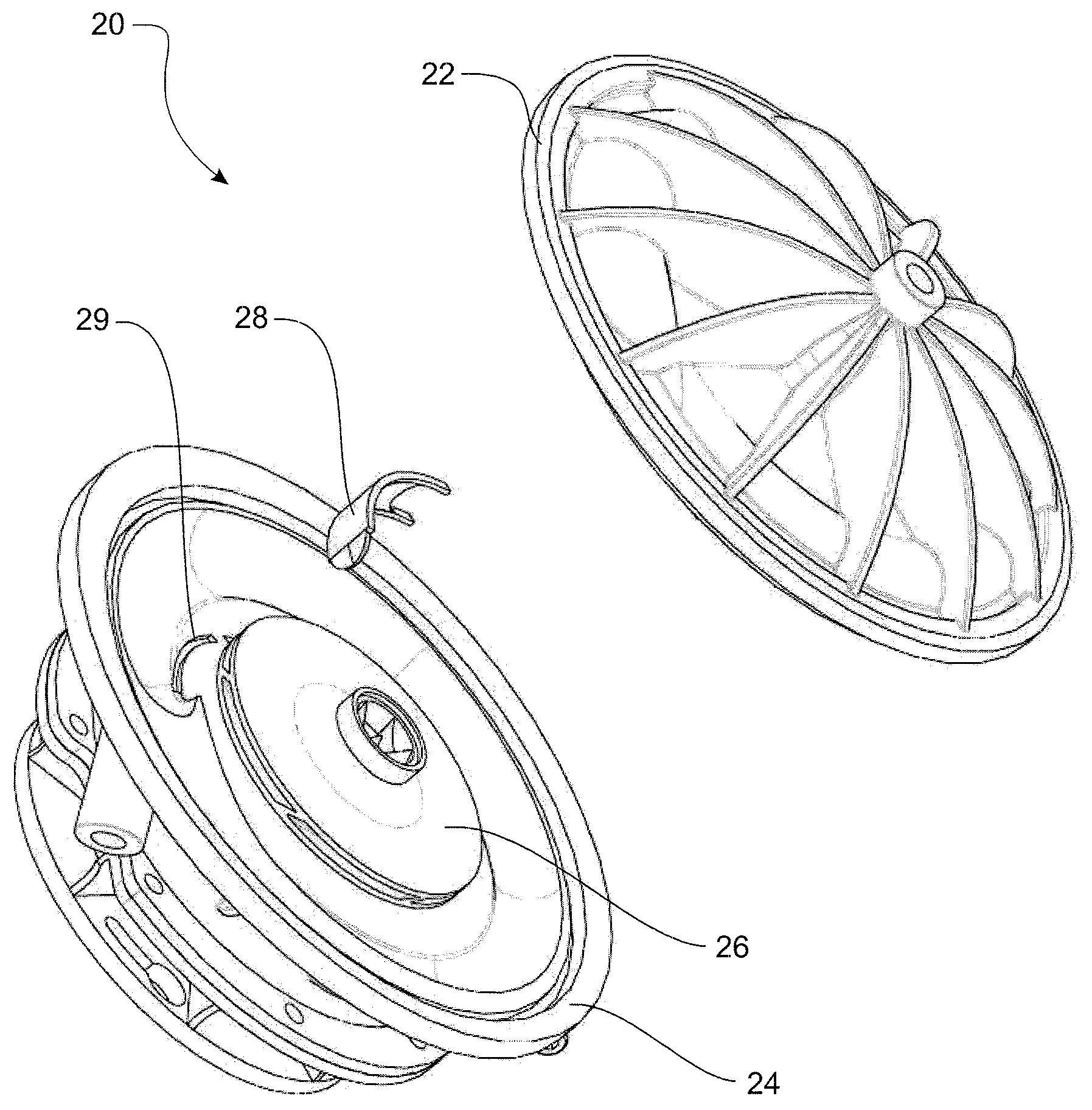
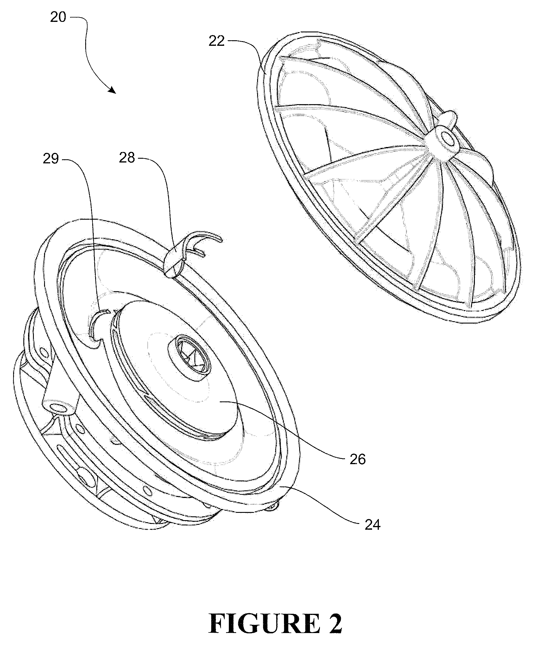
[0032]Referring to FIGS. 2 and 3, the preferred form of the variable pump of the present invention is shown generally as 20. The variable pump 20 comprises two housing halves or casings, a front casing 22 and a back casing 24. When assembled, the front casing 22 and back casing 24 define an interior space in which a removable impeller 26 and a removable cutwater 28 are placed.

[0033]The impeller 26 is received in the pump in any conventional manner, provided it is removable. The cutwater 28 is received in grooves provided in the two housing halves. An example groove is indicated as 29 in the back casing 24 in FIG. 2. A mirrored groove is preferably provided in the front casing 22 so that when the pump is assembled, the cutwater 28 will be firmly secured between the two housing halves. FIG. 3 shows an example mirrored groove 39 in the front casing 22.

[0034]The cutwater 28 is preferably a strip of metal or plastic. A wide range of fixed cutwater sizes may be provided for interchangeabl...


PUM


Abstract

The present invention relates to a centrifugal pump and a method of varying the properties of a centrifugal pump. The centrifugal pump has a pump housing, which in the preferred form comprises a front casing 22 and a back casing 24. The pump also includes an impeller 26. The present invention provides the centrifugal pump with one or more grooves 29 in the housing adjacent the impeller 26. The one or more grooves are adapted to removably receive a cutwater 28.

Description

FIELD OF THE INVENTION[0001]The present invention relates to a variable pump and a method for operating the same. In particular, but not exclusively, the present invention relates to a centrifugal pump having an interchangeable impeller and an interchangeable cutwater for varying the characteristics of the centrifugal pump.BACKGROUND TO THE INVENTION[0002]Centrifugal pumps are used to impart gases and liquids with an increased flow rate or pressure. Referring to FIG. 1, a centrifugal pump typically comprises a pump housing 10 in which an impeller 12 is rotatably positioned. When the impeller 12 is rotated, its blades draw in gas or liquid from an inlet 14.[0003]The rotation of the impeller 12 forces gases or liquids from the inlet 14 toward the volute 16, which collects and directs the gases and liquids toward the outlet 18. The volute 16 may be provided as an expanding cross sectional area that forces high-kinetic-energy water flung from the periphery of the impeller to slow down a...

Claims


Application Information

Patent Timeline
IPC IPC(8): F01D25/24
CPCF04D29/428F04D29/466F04D29/445
Inventor WIGGINS, STEVEN JOHN
Owner HOT WATER INNOVATIONS
Why Eureka
Try Eureka